COLORIMETER

Introduction

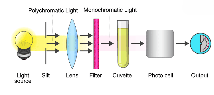
A colorimeter is a laboratory device used to measure the absorbance of light at specific wavelengths in a given solution. Colorimetry is based on Beer-Lambert’s law, which states that the amount of light absorbed by a colored solution is directly proportional to the solution’s concentration and the length of the light path through it. When light passes through a sample solution, part of it is absorbed, while the remaining light is transmitted. By comparing the color intensity of a solute in the sample solution to that of a reference solution with a known solute concentration, we can estimate the concentration of the colored solute in the sample. Colorimeters are commonly used in fields such as water analysis, environmental analysis, and laboratory research.

Colorimeters, if accessible to households, could be used for practical applications like food quality control, water testing, and gardening. For instance, they could help ensure the freshness of fruits based on their color, test the purity of tap water, or analyze soil nutrients for home gardening. These applications could contribute to health, food safety, and environmental conservation efforts at a personal level.

Overview of the Project

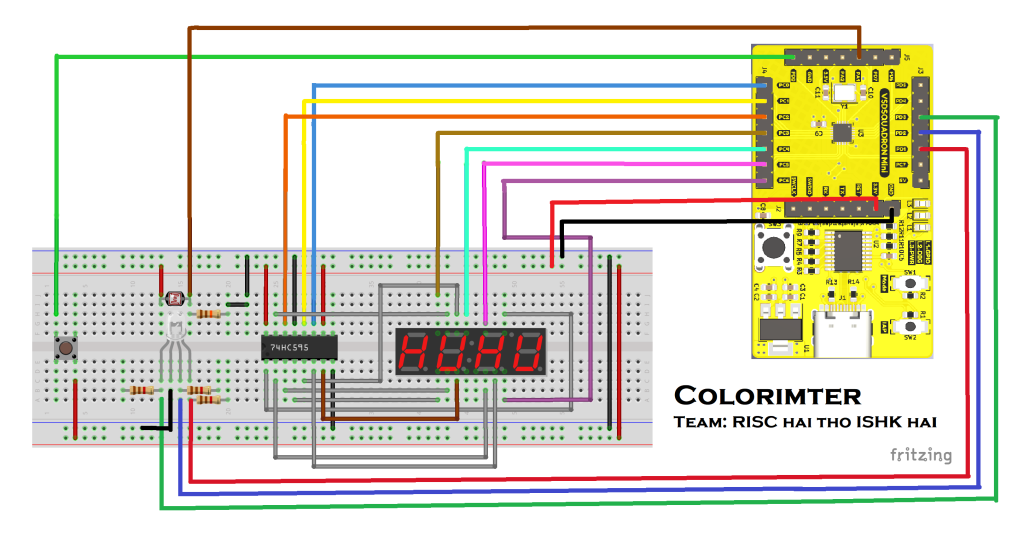
We are developing a colorimeter using an RGB LED to produce a spectrum of wavelengths by adjusting the intensity of the red, green, and blue LEDs individually. The emitted light passes through a solution sample in a cuvette positioned between the LED and a light-dependent resistor (LDR). LDR is a special resistor which creates variying voltage drop across it based on the intensity of incident light. The solution absorbs specific wavelengths based on the solute’s concentration and nature of the solute. Unabsorbed light is incident on the LDR , where voltage variations are recorded to calculate the corresponding intensity of a particular wavelength and hence the intesity across the spectrum. The analysis is performed in a closed black box to eliminate the external light sources from disturbing the analysis. A Zero Analysis is performed with only the pure solvent (e.g., distilled water), prior to performing actual analysis by placing the sample of the solute. Then the difference between the actual analysis and zero analysis is taken. This significantly reduces the the external noise from other light sources and defects in the RGB leds which do not produce the exact wavelength.

The wavelength and light intensity of the light are then displayed on a 4-bit 7-segment display. To efficiently transfer data to the display unit and minimize the number of pins required, we are using a Serial-In-Parallel-Out (SIPO) shift register.

Components Required

ComponentQuantity
VSD Squadron Mini Board1
RGB LED (Common Cathode)1
1.1 KΩ Resistor5
11 KΩ Resistor1
Light Dependent Resistor1
4 Bit Seven Segment Display1
74HC595 IC1
Push Button1

Circuit Connection Diagram

Tables for Pin connection

VSD Squadron Mini74HC595
3.3 VPin 16 (Vcc) and Pin 10 (~Master Reset)
GNDPin 8 (GND) and Pin 13 (~Output Enable)
PC0Pin 11 (Clock)
PC1Pin 12 (Latch Pin)
PC2Pin 14 (Serial Data In)
VSD Squadron Mini4 Bit Seven Segment Display
PC3D1
PC4D2
PC5D3
PC6D4
VSD Squadron MiniRGB LED
PD1Red
PD3Green
PD2Blue
GNDCommon Cathode
VSD Squadron MiniOthers
PD0Push Button (Signal)
PA1LDR (Signal)
GNDPush Button (GND) and LDR (GND)

Working Video

Code

#include <ch32v00x.h>
#include <debug.h>

#define LED_RED GPIO_Pin_4
#define LED_GREEN GPIO_Pin_2
#define LED_BLUE GPIO_Pin_3 

#define GPIO_PORT GPIOC
#define CLOCKPIN GPIO_Pin_0     //Pin 11 CLOCK
#define LATCHPIN GPIO_Pin_1		//Pin 12 latch
#define DATAPIN GPIO_Pin_2		//Pin 14 DataPin
#define DATA_1 GPIO_Pin_3		//D1
#define DATA_2 GPIO_Pin_4		//D2
#define DATA_3 GPIO_Pin_5		//D3
#define DATA_4 GPIO_Pin_6		//D4
#define CLOCK_ENABLE RCC_APB2PeriphClockCmd(RCC_APB2Periph_GPIOC, ENABLE)

#define ANALOG1_PIN     GPIO_Pin_1
#define ANALOG1_PORT    GPIOA

uint16_t adcReading;
int adcFlag, adc_int_val;

unsigned  char table[]={0x02,0x9E,0x24,0x0C,0x98,0x48,0x40,0x1E,0x00,0x08,0x77,0x7c,0x39,0x5e,0x79};
int  count = 2;
const int nbrDigits= 4;
void DisplayDigit(unsigned char num, int  digit);
void DisplayNumber(int number);

unsigned int reference_solution[6], solution[6], diff[6];
int absorbed_color_coeff, absorbed_color;
unsigned int wavelength[]={380, 450, 530, 570, 601, 670};

void shiftout(uint8_t dataPin, uint8_t clockPin, uint8_t bitOrder, uint8_t val)
{
	uint8_t i;

	for (i = 0; i < 8; i++) 
	{
		if (bitOrder == 0)
				GPIO_WriteBit(GPIO_PORT, dataPin, !!(val & (1 << i)));
		else      
				GPIO_WriteBit(GPIO_PORT, dataPin, !!(val & (1 << (7 - i))));
				
		GPIO_WriteBit(GPIO_PORT, CLOCKPIN, 1);
		GPIO_WriteBit(GPIO_PORT, CLOCKPIN, 0);
	}
}


void DisplayNumber(int number)
{    
	if(number == 0)
		DisplayDigit( 0, nbrDigits-1) ; // display 0 in the rightmost digit
	else
	{
		for( int digit = nbrDigits-1; digit  >= 0; digit--)
		{
			if(number > 0)
			{
				DisplayDigit(number % 10, digit) ;
				number = number / 10;
			}
		}
	}

}


void DisplayDigit(unsigned char num, int  digit)
{
	GPIO_WriteBit(GPIO_PORT, LATCHPIN, 0);
	shiftout(DATAPIN, CLOCKPIN, 1, table[num]);
	GPIO_WriteBit(GPIO_PORT, LATCHPIN, 1);
  
    if(digit == 0)
	{
		GPIO_WriteBit(GPIO_PORT, DATA_1, 1);
		Delay_Ms(4);
		GPIO_WriteBit(GPIO_PORT, DATA_1, 0);
	}
    else if(digit == 1)
	{
		GPIO_WriteBit(GPIO_PORT, DATA_2, 1);
		Delay_Ms(4);
		GPIO_WriteBit(GPIO_PORT, DATA_2, 0);
	}
    else if(digit == 2)
	{	
		GPIO_WriteBit(GPIO_PORT, DATA_3, 1);
		Delay_Ms(4);
		GPIO_WriteBit(GPIO_PORT, DATA_3, 0);
	}
    else if(digit == 3)
	{
		GPIO_WriteBit(GPIO_PORT, DATA_4, 1);
		Delay_Ms(4);
		GPIO_WriteBit(GPIO_PORT, DATA_4, 0);
	}  
}

void ADCConfig(void)
{
    ADC_InitTypeDef ADC_InitStructure = {0};
    GPIO_InitTypeDef GPIO_InitStructureADC = {0};
    NVIC_InitTypeDef NVIC_InitStructure = {0};

    RCC_APB2PeriphClockCmd(RCC_APB2Periph_GPIOA, ENABLE);
    RCC_APB2PeriphClockCmd(RCC_APB2Periph_ADC1, ENABLE);
    RCC_ADCCLKConfig(RCC_PCLK2_Div8);

    GPIO_InitStructureADC.GPIO_Pin = ANALOG1_PIN;
    GPIO_InitStructureADC.GPIO_Mode = GPIO_Mode_AIN;
    GPIO_Init(ANALOG1_PORT, &GPIO_InitStructureADC);

    ADC_DeInit(ADC1);
    ADC_InitStructure.ADC_Mode = ADC_Mode_Independent;
    ADC_InitStructure.ADC_ScanConvMode = DISABLE;
    ADC_InitStructure.ADC_ContinuousConvMode = DISABLE;
    ADC_InitStructure.ADC_ExternalTrigConv = ADC_ExternalTrigInjecConv_None;
    ADC_InitStructure.ADC_DataAlign = ADC_DataAlign_Right;
    ADC_InitStructure.ADC_NbrOfChannel = 1;
    ADC_Init(ADC1, &ADC_InitStructure);

    ADC_InjectedSequencerLengthConfig(ADC1, 1);
    ADC_InjectedChannelConfig(ADC1, ADC_Channel_1, 1, ADC_SampleTime_241Cycles);
    ADC_ExternalTrigInjectedConvCmd(ADC1, DISABLE);

    NVIC_InitStructure.NVIC_IRQChannel = ADC_IRQn;
    NVIC_InitStructure.NVIC_IRQChannelPreemptionPriority = 2;
    NVIC_InitStructure.NVIC_IRQChannelSubPriority = 0;
    NVIC_InitStructure.NVIC_IRQChannelCmd = ENABLE;
    NVIC_Init(&NVIC_InitStructure);

    ADC_Calibration_Vol(ADC1, ADC_CALVOL_50PERCENT);
    ADC_ITConfig(ADC1, ADC_IT_JEOC, ENABLE);
    ADC_Cmd(ADC1, ENABLE);

    ADC_ResetCalibration(ADC1);

    while (ADC_GetResetCalibrationStatus(ADC1))
	{

	}

    ADC_StartCalibration(ADC1);

    while (ADC_GetCalibrationStatus(ADC1))
	{

	}
}

int ADCVal(void)
{
	ADC_SoftwareStartInjectedConvCmd(ADC1, ENABLE);
    if(adcFlag ==1)
	{
		adcReading = ADC_GetInjectedConversionValue(ADC1, ADC_InjectedChannel_1);
		adcFlag = 0;
	}
    adc_int_val=adcReading;
	return adc_int_val;
}

void ADC1_IRQHandler() __attribute__((interrupt("WCH-Interrupt-fast")));
void NMI_Handler(void) __attribute__((interrupt("WCH-Interrupt-fast")));
void HardFault_Handler(void) __attribute__((interrupt("WCH-Interrupt-fast")));
void Delay_Init(void);
void Delay_Ms(uint32_t n);

int main(void)
{
    NVIC_PriorityGroupConfig(NVIC_PriorityGroup_2);
    SystemCoreClockUpdate();
    Delay_Init();
    
    GPIO_InitTypeDef GPIO_InitStructure;
    RCC_APB2PeriphClockCmd(RCC_APB2Periph_GPIOD, ENABLE);
    GPIO_InitStructure.GPIO_Pin = LED_RED | LED_GREEN | LED_BLUE ;
    GPIO_InitStructure.GPIO_Mode = GPIO_Mode_Out_PP;
    GPIO_InitStructure.GPIO_Speed = GPIO_Speed_50MHz;
    GPIO_Init(GPIOD, &GPIO_InitStructure);
    
    GPIO_InitTypeDef GPIO_InitStructurePB;
    GPIO_InitStructurePB.GPIO_Pin = GPIO_Pin_0;
    GPIO_InitStructurePB.GPIO_Mode = GPIO_Mode_IPU;
    GPIO_InitStructurePB.GPIO_Speed = GPIO_Speed_50MHz;
    GPIO_Init(GPIOD, &GPIO_InitStructurePB);
    
    GPIO_InitTypeDef GPIO_InitStructure0 = {0};
    CLOCK_ENABLE;
    GPIO_InitStructure0.GPIO_Pin = CLOCKPIN;
    GPIO_InitStructure0.GPIO_Mode = GPIO_Mode_Out_PP;
    GPIO_InitStructure0.GPIO_Speed = GPIO_Speed_50MHz;
    GPIO_Init(GPIO_PORT, &GPIO_InitStructure0);
    
    GPIO_InitTypeDef GPIO_InitStructure1 = {0};
    CLOCK_ENABLE;
    GPIO_InitStructure1.GPIO_Pin = DATAPIN;
    GPIO_InitStructure1.GPIO_Mode = GPIO_Mode_Out_PP;
    GPIO_InitStructure1.GPIO_Speed = GPIO_Speed_50MHz;
    GPIO_Init(GPIO_PORT, &GPIO_InitStructure1);
    
    GPIO_InitTypeDef GPIO_InitStructure3 = {0};
    CLOCK_ENABLE;
    GPIO_InitStructure3.GPIO_Pin = LATCHPIN;
    GPIO_InitStructure3.GPIO_Mode = GPIO_Mode_Out_PP;
    GPIO_InitStructure3.GPIO_Speed = GPIO_Speed_50MHz;
    GPIO_Init(GPIO_PORT, &GPIO_InitStructure3);
    
    GPIO_InitTypeDef GPIO_InitStructure4 = {0};
    CLOCK_ENABLE;
    GPIO_InitStructure4.GPIO_Pin = DATA_1;
    GPIO_InitStructure4.GPIO_Mode = GPIO_Mode_Out_PP;
    GPIO_InitStructure4.GPIO_Speed = GPIO_Speed_50MHz;
    GPIO_Init(GPIO_PORT, &GPIO_InitStructure4);
    
    GPIO_InitTypeDef GPIO_InitStructure5 = {0};
    CLOCK_ENABLE;
    GPIO_InitStructure5.GPIO_Pin = DATA_2;
    GPIO_InitStructure5.GPIO_Mode = GPIO_Mode_Out_PP;
    GPIO_InitStructure5.GPIO_Speed = GPIO_Speed_50MHz;
    GPIO_Init(GPIO_PORT, &GPIO_InitStructure5);
    
    GPIO_InitTypeDef GPIO_InitStructure6 = {0};
    CLOCK_ENABLE;
    GPIO_InitStructure6.GPIO_Pin = DATA_3;
    GPIO_InitStructure6.GPIO_Mode = GPIO_Mode_Out_PP;
    GPIO_InitStructure6.GPIO_Speed = GPIO_Speed_50MHz;
    GPIO_Init(GPIO_PORT, &GPIO_InitStructure6);
    
    GPIO_InitTypeDef GPIO_InitStructure7 = {0};
    CLOCK_ENABLE;
    GPIO_InitStructure7.GPIO_Pin = DATA_4;
    GPIO_InitStructure7.GPIO_Mode = GPIO_Mode_Out_PP;
    GPIO_InitStructure7.GPIO_Speed = GPIO_Speed_50MHz;
    GPIO_Init(GPIO_PORT, &GPIO_InitStructure7);
    
    ADCConfig();
    
    GPIO_WriteBit(GPIOD, LED_RED|LED_BLUE, Bit_SET);
    GPIO_WriteBit(GPIOD, LED_GREEN, Bit_RESET);
    Delay_Ms(500);
    reference_solution[0]=ADCVal();
    for(int i=0; i<150; i++)
      DisplayNumber(reference_solution[0]);			
    
    GPIO_WriteBit(GPIOD, LED_BLUE, Bit_SET);
    GPIO_WriteBit(GPIOD, LED_RED|LED_GREEN, Bit_RESET);
    Delay_Ms(500);
    reference_solution[1]=ADCVal();
    for(int i=0; i<150; i++)
      DisplayNumber(reference_solution[1]);
    
    GPIO_WriteBit(GPIOD, LED_BLUE|LED_GREEN, Bit_SET);
    GPIO_WriteBit(GPIOD, LED_RED, Bit_RESET);
    Delay_Ms(500);
    reference_solution[2]=ADCVal();
    for(int i=0; i<150; i++)
      DisplayNumber(reference_solution[2]);
        
    GPIO_WriteBit(GPIOD, LED_GREEN, Bit_SET);
    GPIO_WriteBit(GPIOD, LED_BLUE|LED_RED, Bit_RESET);
    Delay_Ms(500);
    reference_solution[3]=ADCVal();
    for(int i=0; i<150; i++)
      DisplayNumber(reference_solution[3]);
      
    GPIO_WriteBit(GPIOD, LED_RED|LED_GREEN, Bit_SET);
    GPIO_WriteBit(GPIOD, LED_BLUE, Bit_RESET);
    Delay_Ms(500);
    reference_solution[4]=ADCVal();
    for(int i=0; i<150; i++)
      DisplayNumber(reference_solution[4]);
      
    GPIO_WriteBit(GPIOD, LED_RED, Bit_SET);
    GPIO_WriteBit(GPIOD, LED_GREEN|LED_BLUE, Bit_RESET);
    Delay_Ms(500);
    reference_solution[5]=ADCVal();
    for(int i=0; i<150; i++)
      DisplayNumber(reference_solution[5]);	
    
    while(GPIO_ReadInputDataBit(GPIOD, GPIO_Pin_0)!=0)
    {
      Delay_Ms(50);
    }
    
    GPIO_WriteBit(GPIOD, LED_RED|LED_BLUE, Bit_SET);
    GPIO_WriteBit(GPIOD, LED_GREEN, Bit_RESET);
    Delay_Ms(500);
    solution[0]=ADCVal();
    for(int i=0; i<150; i++)
      DisplayNumber(solution[0]);			
    
    GPIO_WriteBit(GPIOD, LED_BLUE, Bit_SET);
    GPIO_WriteBit(GPIOD, LED_RED|LED_GREEN, Bit_RESET);
    Delay_Ms(500);
    solution[1]=ADCVal();
    for(int i=0; i<150; i++)
      DisplayNumber(solution[1]);
    
    GPIO_WriteBit(GPIOD, LED_BLUE|LED_GREEN, Bit_SET);
    GPIO_WriteBit(GPIOD, LED_RED, Bit_RESET);
    Delay_Ms(500);
    solution[2]=ADCVal();
    for(int i=0; i<150; i++)
      DisplayNumber(solution[2]);
        
    GPIO_WriteBit(GPIOD, LED_GREEN, Bit_SET);
    GPIO_WriteBit(GPIOD, LED_BLUE|LED_RED, Bit_RESET);
    Delay_Ms(500);
    solution[3]=ADCVal();
    for(int i=0; i<150; i++)
      DisplayNumber(solution[3]);
      
    GPIO_WriteBit(GPIOD, LED_RED|LED_GREEN, Bit_SET);
    GPIO_WriteBit(GPIOD, LED_BLUE, Bit_RESET);
    Delay_Ms(500);
    solution[4]=ADCVal();
    for(int i=0; i<150; i++)
      DisplayNumber(solution[4]);
      
    GPIO_WriteBit(GPIOD, LED_RED, Bit_SET);
    GPIO_WriteBit(GPIOD, LED_GREEN|LED_BLUE, Bit_RESET);
    Delay_Ms(500);
    solution[5]=ADCVal();
    for(int i=0; i<150; i++)
      DisplayNumber(solution[5]);
    
    absorbed_color_coeff=0;
    for(int i=0; i<6; i++)
    {
      diff[i]=solution[i]-reference_solution[i];
      if(diff[i]>diff[absorbed_color_coeff])
        absorbed_color_coeff=i;
    }
    absorbed_color=wavelength[absorbed_color_coeff];
    for(int i=0;i<250;i++)
      DisplayNumber(absorbed_color);
}

void ADC1_IRQHandler()
{
    if (ADC_GetITStatus(ADC1, ADC_IT_JEOC) == SET)
    {
        adcFlag = 1;
        ADC_ClearITPendingBit(ADC1, ADC_IT_JEOC);
    }
}

void NMI_Handler(void)
{	

}

void HardFault_Handler(void)
{
	while (1)
	{
	}
}

Registration for Ethical RISC-V IoT Workshop

Welcome to Ethical RISC-V IoT Workshop

The “Ethical RISC-V IoT Workshop” at IIIT Bangalore, organized in collaboration with VSD, is a structured, educational competition aimed at exploring real-world challenges in IoT and embedded systems. Participants progress through three stages: building an application, injecting and managing faults, and enhancing application security. The event spans from May 9 to June 15, 2024, culminating in a showcase of top innovations and an award ceremony. This hands-on hackathon emphasizes learning, testing, and securing applications in a collaborative and competitive environment.

Rules :
  1. Only for Indian Student whose college is registered under VTU
  2. Only team of 2 members can Register
  3. Use only VSDSquadron Mini resources for product development
Awards :
  1. Prize money for final 10 Team
  2. 3 Winner team’s Product will be evaluated for Incubation
  3. 7 consolation prizes
  4. Completion Certificate to final round qualifier
  5. Chance to build a Proud Secured RISC-V Platform for India

Date for Registration : 9th May - 22nd May, 2024
Hackathon Inauguration : 23rd May 2024

VSDSquadron (Educational Board)

VSDSquadron, a cutting-edge development board based on the RISC-V architecture that is fully open-source. This board presents an exceptional opportunity for individuals to learn about RISC-V and VLSI chip design utilizing only open-source tools, starting from the RTL and extending all the way to the GDSII. The possibilities for learning and advancement with this technology are limitless.

Furthermore, the RISC-V chips on these boards should be open for VLSI chip design learning, allowing you to explore PNR, standard cells, and layout design. And guess what? vsdsquadron is the perfect solution for all your needs! With its comprehensive documentation and scalable labs, thousands of students can learn and grow together.

VSD HDP (Hardware Design Program) Duration-10 Week

With VSD Hardware Design Program (VSD-HDP),  you have the opportunity to push the boundaries of what exist in open source and establish the new benchmark for tomorrow.

It will leverage your degree in Electrical or Computer Engineering to work with

  • Programmable logic
  • Analog/ digital IP
  • RISC-V
  • Architecture & microprocessors
  • ASICs and SoCs on high-density digital or RF circuit cards
  • Gain hands-on knowledge during design validation and system integration.

Sounds exciting to just get started with expert mentors, doesn’t it? But we are looking for the next generation of learners, inventors, rebels, risk takers, and pioneers.

“Spend your summer working in the future !!”

Outcomes of VSD Online Research IP Design Internship Program

  1. Job opportunities in Semiconductor Industry
  2. Research work can be submitted to VLSI International journals
  3. Participate in Semiconductor International Conference with Internship Research Work
  4. Paper Publications in IEEE Conference and SIG groups
  5. Tape out opportunity and IP Royalty
  6. Interact with world class Semiconductor designer and researchers
  7. Academic professions where more research projects are encouraged.
  8. All the above research and publication work will help colleges and institutes to improve accreditation levels.

Know More Information

VSD – Intelligent Assessment Technology (VSD-IAT)

VSD – Intelligent Assessment Technology (VSD-IAT) is expertly built training platform and is suited for designer requirements. Semiconductor companies understand the value of training automation and Engineer performance enhancement, and do not need to be convinced of the impact of a virtual platform for learning. VSD trainings are quick, relevant, and easy to access from any device at any time zone.

VSD Intern Webinars

VSD Interns made it happen !!

VSD is working towards creating innovative talent pool who are ready to develop design and products for the new tech world. VSD believes in “Learning by doing principle” , and always prepare the student to apply the knowledge learned in the workshops, webinars and courses. We always push our students to work on new designs, test it and work continuously till it becomes the best performing design. Any student who enrolls to VSD community starts working with small design and grows with us and develops a tapeout level design with complete honesty and dedication towards the Work !!

Check out VSD Interns Achievement!

VSDOpen Online Conference

Welcome to the World’s only online conference in Semiconductor Industry VSDOpen Conference. With enormous support and global presence of audience from different segments of industrial lobby and academia made a highly successful event. Evolution is change in the genetic makeup of a population over time, online conference is one kind evaluation everyone adapt soon. 

  • VSDOpen 2022 is an online conference to share open-source research with the community and promote  hardware design mostly done by the student community.
  • VSDOpen 2022 is based on the theme “How to lower the cost to learn, build, and tapeout chips ?”  , which will provide a platform to community to build stronger designs and strengthen the future of Chip design.
  • VSDOpen is envisioned to create a community based revolution in semiconductor hardware technology.
  • The open source attitude is required to bring out the talent and innovation from the community who are in remote part of world and have least access to the technologies.  And now Google support will help to bring the vision to execution by VSD team

VSD Online Course by Kunal Ghosh

VSD offers online course in complete spectrum of vlsi backend flow from RTL design, synthesis and Verification, SoC planning and design, Sign-off analysis, IP Design, CAD/EDA automation and basic UNIX/IT, Introduction to latest technology – RISC-V, Machine intelligence in EDA/CAD, VLSI Interview FAQ’s.

Current Reach – As of 2021, VSD and its partners have released 41 online VLSI courses and was successfully able to teach  ~35900 Unique students around 151 countries in 47 different languages, through its unique info-graphical and technology mediated learning methods.

Enquiry Form