Introduction
Parkinson’s Disease is Neurodegenerative disorder that mostly presents in later life with generalized slowing of movements .Freezing of gait (FOG) is one of the most troublesome symptoms of Parkinson’s disease, affecting more than 50% of patients in advanced stages of the disease. Our idea proposes a solution for Parkinson’s disease involving supportive footwear.The footwear analyzes foot pressure of patient using 4 pressure sensors.Based upon analysis it alerts or gives motivation to patient on adverse condition.
An additional feature of this project is the integration of an LED indicator and buzzer to provide feedback on the gait status.
Overview
This technology-driven approach offers a practical and user-friendly solution for managing Parkinson’s disease symptoms, specifically addressing the challenging issue of Freezing of Gait (FOG). The supportive footwear integrates four pressure sensors to analyze foot pressure in real time. Based on this analysis, the system can alert or motivate the patient during adverse conditions, potentially improving mobility and quality of life.
Additionally, the footwear features an LED indicator and a buzzer to provide immediate feedback on gait status. This real-time feedback can help patients and caregivers monitor and manage FOG episodes more effectively, contributing to better symptom management and increased safety.
By leveraging advanced sensor technology and real-time data processing, this project showcases the potential to enhance the lives of Parkinson’s disease patients. Its implementation holds promise for improving mobility, safety, and overall quality of life, demonstrating a significant step forward in supportive healthcare technology for neurodegenerative disorders.
Components Required
- VSD Squadron Mini developement board with CH32V003F4U6 chip with 32-bit RISC-V core based on RV32EC instruction set
- Velostat sensor
- Bread Board
- Jumper Wires
- LED
- Resistors
Circuit Connection Diagram
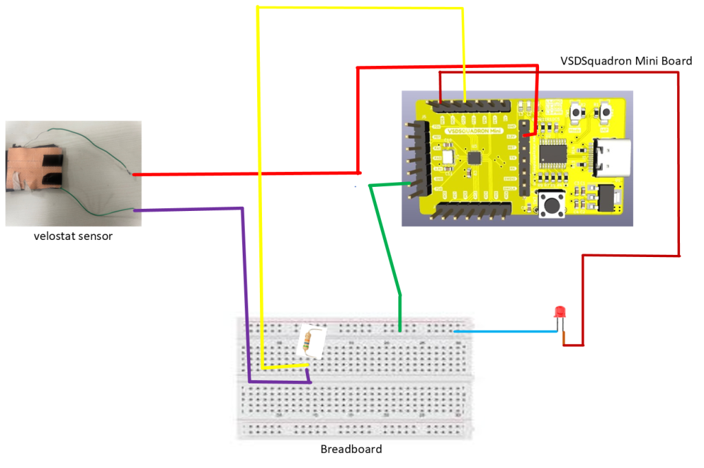
Pin Connections
| Velostat | VSD Squadron Mini |
|---|---|
| Digital | PD2 |
| VCC | 3.3V |
| VSD Squadron Mini | LEDs |
|---|---|
| PD4 | LED Red |
Code
#include "debug.h"
#include <math.h> // Include math.h for sqrt function

#define ARRAY_SIZE 10

void ADC_Function_Init(void)
{
    ADC_InitTypeDef  ADC_InitStructure = {0};
    GPIO_InitTypeDef GPIO_InitStructure = {0};
    NVIC_InitTypeDef NVIC_InitStructure = {0};

    RCC_APB2PeriphClockCmd(RCC_APB2Periph_GPIOC, ENABLE);
    RCC_APB2PeriphClockCmd(RCC_APB2Periph_GPIOA, ENABLE); // Enable clock for GPIOA
    RCC_APB2PeriphClockCmd(RCC_APB2Periph_GPIOD, ENABLE); // Enable clock for GPIOD
    RCC_APB2PeriphClockCmd(RCC_APB2Periph_ADC1, ENABLE);
    RCC_ADCCLKConfig(RCC_PCLK2_Div8);

    // Configure PC4 (ADC Channel 2)
    GPIO_InitStructure.GPIO_Pin = GPIO_Pin_4;
    GPIO_InitStructure.GPIO_Mode = GPIO_Mode_AIN;
    GPIO_Init(GPIOC, &GPIO_InitStructure);

    // Configure PA1 (ADC Channel 1)
    GPIO_InitStructure.GPIO_Pin = GPIO_Pin_1;
    GPIO_Init(GPIOA, &GPIO_InitStructure);

    // Configure PA2 (ADC Channel 2)
    GPIO_InitStructure.GPIO_Pin = GPIO_Pin_2;
    GPIO_Init(GPIOA, &GPIO_InitStructure);

    // Configure PD2 (ADC Channel 3)
    GPIO_InitStructure.GPIO_Pin = GPIO_Pin_2;
    GPIO_Init(GPIOD, &GPIO_InitStructure);

    ADC_DeInit(ADC1);
    ADC_InitStructure.ADC_Mode = ADC_Mode_Independent;
    ADC_InitStructure.ADC_ScanConvMode = DISABLE;
    ADC_InitStructure.ADC_ContinuousConvMode = DISABLE;
    ADC_InitStructure.ADC_ExternalTrigConv = ADC_ExternalTrigConv_None;
    ADC_InitStructure.ADC_DataAlign = ADC_DataAlign_Right;
    ADC_InitStructure.ADC_NbrOfChannel = 1;
    ADC_Init(ADC1, &ADC_InitStructure);

    // Configure channels with same sample time
    ADC_RegularChannelConfig(ADC1, ADC_Channel_2, 1, ADC_SampleTime_241Cycles);
    ADC_RegularChannelConfig(ADC1, ADC_Channel_1, 1, ADC_SampleTime_241Cycles); // Configure Channel 1
    ADC_RegularChannelConfig(ADC1, ADC_Channel_2, 1, ADC_SampleTime_241Cycles); // Configure Channel 2
    ADC_RegularChannelConfig(ADC1, ADC_Channel_3, 1, ADC_SampleTime_241Cycles); // Configure Channel 3

    /* Higher Threshold:900, Lower Threshold:500 */
    ADC_AnalogWatchdogThresholdsConfig(ADC1, 900, 500);
    ADC_AnalogWatchdogSingleChannelConfig(ADC1, ADC_Channel_2);
    ADC_AnalogWatchdogCmd(ADC1, ADC_AnalogWatchdog_SingleRegEnable);

    NVIC_InitStructure.NVIC_IRQChannel = ADC_IRQn;
    NVIC_InitStructure.NVIC_IRQChannelPreemptionPriority = 0;
    NVIC_InitStructure.NVIC_IRQChannelSubPriority = 1;
    NVIC_InitStructure.NVIC_IRQChannelCmd = ENABLE;
    NVIC_Init(&NVIC_InitStructure);

    ADC_Calibration_Vol(ADC1, ADC_CALVOL_50PERCENT);
    ADC_ITConfig(ADC1, ADC_IT_AWD, ENABLE);
    ADC_Cmd(ADC1, ENABLE);

    ADC_ResetCalibration(ADC1);
    while(ADC_GetResetCalibrationStatus(ADC1));
    ADC_StartCalibration(ADC1);
    while(ADC_GetCalibrationStatus(ADC1));
}

void LED_Function_Init(void)
{
    GPIO_InitTypeDef GPIO_InitStructure = {0};

    RCC_APB2PeriphClockCmd(RCC_APB2Periph_GPIOD, ENABLE);

    GPIO_InitStructure.GPIO_Pin = GPIO_Pin_4;
    GPIO_InitStructure.GPIO_Mode = GPIO_Mode_Out_PP;
    GPIO_InitStructure.GPIO_Speed = GPIO_Speed_50MHz;
    GPIO_Init(GPIOD, &GPIO_InitStructure);
}

u16 Get_ADC_Val(u8 ch)
{
    u16 val;

    ADC_RegularChannelConfig(ADC1, ch, 1, ADC_SampleTime_241Cycles); // Select channel
    ADC_SoftwareStartConvCmd(ADC1, ENABLE);

    while(!ADC_GetFlagStatus(ADC1, ADC_FLAG_EOC));

    val = ADC_GetConversionValue(ADC1);

    return val;
}

int Calculate_Mean(u16 values[], int size)
{
    int sum = 0;
    for (int i = 0; i < size; i++)
    {
        sum += values[i];
    }
    return sum / size;
}


int Calculate_Variance(u16 values[], int size, int mean)
{
    int variance = 0;
    for (int i = 0; i < size; i++)
    {
        variance += (values[i] - mean) * (values[i] - mean);
    }
    return variance / size;
}


int Calculate_Max(u16 values[], int size)
{
    int max = values[0];
    for (int i = 1; i < size; i++)
    {
        if (values[i] > max)
        {
            max = values[i];
        }
    }
    return max;
}


int Calculate_Min(u16 values[], int size)
{
    int min = values[0];
    for (int i = 1; i < size; i++)
    {
        if (values[i] < min)
        {
            min = values[i];
        }
    }
    return min;
}


int main(void)
{
    u16 ADC_val1, ADC_val2, ADC_val3, ADC_val4;
    u16 values_PC4[ARRAY_SIZE], values_PA1[ARRAY_SIZE], values_PA2[ARRAY_SIZE], values_PD2[ARRAY_SIZE];  // Arrays to store 10 values for each sensor
    int count = 0;  // Counter to keep track of the number of values stored

    NVIC_PriorityGroupConfig(NVIC_PriorityGroup_1);
    SystemCoreClockUpdate();
    Delay_Init();

    USART_Printf_Init(9600);
    printf("SystemClk:%d\r\n", SystemCoreClock);
    printf( "ChipID:%08x\r\n", DBGMCU_GetDEVID() );

    ADC_Function_Init();
    LED_Function_Init(); // Initialize LED

    while(1)
    {
        ADC_val1 = Get_ADC_Val(ADC_Channel_2); // Get value from PC4
        ADC_val2 = Get_ADC_Val(ADC_Channel_1); // Get value from PA1
        ADC_val3 = Get_ADC_Val(ADC_Channel_2); // Get value from PA2
        ADC_val4 = Get_ADC_Val(ADC_Channel_3); // Get value from PD2
        Delay_Ms(200);
        // printf("PC4:%04d PA1:%04d PA2:%04d PD2:%04d\r\n", ADC_val1, ADC_val2, ADC_val3, ADC_val4);

        // Store the values in the arrays
        values_PC4[count] = ADC_val1;
        values_PA1[count] = ADC_val2;
        values_PA2[count] = ADC_val3;
        values_PD2[count] = ADC_val4;

        count++;

        // If the arrays are full, calculate and print the statistics
        if (count == ARRAY_SIZE)
        {
            int mean_PC4 = Calculate_Mean(values_PC4, ARRAY_SIZE);
            int mean_PA1 = Calculate_Mean(values_PA1, ARRAY_SIZE);
            int mean_PA2 = Calculate_Mean(values_PA2, ARRAY_SIZE);
            int mean_PD2 = Calculate_Mean(values_PD2, ARRAY_SIZE);

            int var_PC4 = Calculate_Variance(values_PC4, ARRAY_SIZE, mean_PC4);
            int var_PA1 = Calculate_Variance(values_PA1, ARRAY_SIZE, mean_PA1);
            int var_PA2 = Calculate_Variance(values_PA2, ARRAY_SIZE, mean_PA2);
            int var_PD2 = Calculate_Variance(values_PD2, ARRAY_SIZE, mean_PD2);

            int max_PC4 = Calculate_Max(values_PC4, ARRAY_SIZE);
            int min_PC4 = Calculate_Min(values_PC4, ARRAY_SIZE);

            int max_PA1 = Calculate_Max(values_PA1, ARRAY_SIZE);
            int min_PA1 = Calculate_Min(values_PA1, ARRAY_SIZE);

            int max_PA2 = Calculate_Max(values_PA2, ARRAY_SIZE);
            int min_PA2 = Calculate_Min(values_PA2, ARRAY_SIZE);

            int max_PD2 = Calculate_Max(values_PD2, ARRAY_SIZE);
            int min_PD2 = Calculate_Min(values_PD2, ARRAY_SIZE);

            printf("Statistics:\r\n");
            printf("PC4 - Mean: %d, Variance: %d, Max: %d, Min: %d\r\n", mean_PC4, var_PC4, max_PC4, min_PC4);
            printf("PA1 - Mean: %d, Variance: %d, Max: %d, Min: %d\r\n", mean_PA1, var_PA1, max_PA1, min_PA1);
            printf("PA2 - Mean: %d, Variance: %d, Max: %d, Min: %d\r\n", mean_PA2, var_PA2, max_PA2, min_PA2);
            printf("PD2 - Mean: %d, Variance: %d, Max: %d, Min: %d\r\n", mean_PD2, var_PD2, max_PD2, min_PD2);

            // Check and print the state
            if (var_PC4 > 10000 && var_PA1 > 10000 && var_PA2 > 10000)
            {
                printf("State: Walking\r\n");
                GPIO_ResetBits(GPIOD, GPIO_Pin_4);
            }
            else if (var_PC4 >= 100 && var_PC4 <= 10000 &&
                     var_PA1 >= 100 && var_PA1 <= 10000 &&
                     var_PA2 >= 100 && var_PA2 <= 10000 )
            {
                printf("State: Shaking\r\n");
                GPIO_SetBits(GPIOD, GPIO_Pin_4);
            }
            else
            {
                printf("State: Standing\r\n");
                GPIO_ResetBits(GPIOD, GPIO_Pin_4);
            }

            count = 0;  // Reset the count to start storing new values
        }
    }
}

void ADC1_IRQHandler(void) _attribute_((interrupt("WCH-Interrupt-fast")));
/***********************
 * @fn      ADC1_IRQHandler
 *
 * @brief   This function handles analog watchdog exception.
 *
 * @return  none
 */
void ADC1_IRQHandler(void)
{
    if(ADC_GetITStatus( ADC1, ADC_IT_AWD)){
        // printf( "Enter AnalogWatchdog Interrupt\r\n" );
    }

    ADC_ClearITPendingBit( ADC1, ADC_IT_AWD);
}
Video
Fault Injected in input(Sensor analog values)
The sensor values after ADC ranges between 0 to 1023 that is 10bits.If there is attack on one or more analog values of sensor then output get affected.
Fault
Fault Secured
We checked analog values which we are storing in array of size 10 for each sensor for predicting state.If one or more values but total count less than 5 are corrupted then we replace them by mean of other values.If count of corrupted values is greater than 5 then we discard these reading for prediction.
Secured Code
/**** (C) COPYRIGHT *****
 * File Name          : main.c
 * Author             : WCH
 * Version            : V1.0.0
 * Date               : 2023/12/22
 * Description        : Main program body.
 *********
 * Copyright (c) 2021 Nanjing Qinheng Microelectronics Co., Ltd.
 * Attention: This software (modified or not) and binary are used for
 * microcontroller manufactured by Nanjing Qinheng Microelectronics.
 *********/

/*
 *@Note
 *Analog watchdog routine:
 *ADC channels (PC4, PA1, PA2, PD2), detect that the ADC conversion data on the rule group channels is
 *outside 500 - 900 and trigger the simulation Watchdog interrupt.
 *
*/

#include "debug.h"
#include <math.h> // Include math.h for sqrt function
#define FAULT_THRESHOLD 5
#define ARRAY_SIZE 10

/*********
 * @fn      ADC_Function_Init
 *
 * @brief   Initializes ADC collection.
 *
 * @return  none
 */
void ADC_Function_Init(void)
{
    ADC_InitTypeDef  ADC_InitStructure = {0};
    GPIO_InitTypeDef GPIO_InitStructure = {0};
    NVIC_InitTypeDef NVIC_InitStructure = {0};

    RCC_APB2PeriphClockCmd(RCC_APB2Periph_GPIOC, ENABLE);
    RCC_APB2PeriphClockCmd(RCC_APB2Periph_GPIOA, ENABLE); // Enable clock for GPIOA
    RCC_APB2PeriphClockCmd(RCC_APB2Periph_GPIOD, ENABLE); // Enable clock for GPIOD
    RCC_APB2PeriphClockCmd(RCC_APB2Periph_ADC1, ENABLE);
    RCC_ADCCLKConfig(RCC_PCLK2_Div8);

    // Configure PC4 (ADC Channel 2)
    GPIO_InitStructure.GPIO_Pin = GPIO_Pin_4;
    GPIO_InitStructure.GPIO_Mode = GPIO_Mode_AIN;
    GPIO_Init(GPIOC, &GPIO_InitStructure);

    // Configure PA1 (ADC Channel 1)
    GPIO_InitStructure.GPIO_Pin = GPIO_Pin_1;
    GPIO_Init(GPIOA, &GPIO_InitStructure);

    // Configure PA2 (ADC Channel 2)
    GPIO_InitStructure.GPIO_Pin = GPIO_Pin_2;
    GPIO_Init(GPIOA, &GPIO_InitStructure);

    // Configure PD2 (ADC Channel 3)
    GPIO_InitStructure.GPIO_Pin = GPIO_Pin_2;
    GPIO_Init(GPIOD, &GPIO_InitStructure);

    ADC_DeInit(ADC1);
    ADC_InitStructure.ADC_Mode = ADC_Mode_Independent;
    ADC_InitStructure.ADC_ScanConvMode = DISABLE;
    ADC_InitStructure.ADC_ContinuousConvMode = DISABLE;
    ADC_InitStructure.ADC_ExternalTrigConv = ADC_ExternalTrigConv_None;
    ADC_InitStructure.ADC_DataAlign = ADC_DataAlign_Right;
    ADC_InitStructure.ADC_NbrOfChannel = 1;
    ADC_Init(ADC1, &ADC_InitStructure);

    // Configure channels with same sample time
    ADC_RegularChannelConfig(ADC1, ADC_Channel_2, 1, ADC_SampleTime_241Cycles);
    ADC_RegularChannelConfig(ADC1, ADC_Channel_1, 1, ADC_SampleTime_241Cycles); // Configure Channel 1
    ADC_RegularChannelConfig(ADC1, ADC_Channel_2, 1, ADC_SampleTime_241Cycles); // Configure Channel 2
    ADC_RegularChannelConfig(ADC1, ADC_Channel_3, 1, ADC_SampleTime_241Cycles); // Configure Channel 3

    /* Higher Threshold:900, Lower Threshold:500 */
    ADC_AnalogWatchdogThresholdsConfig(ADC1, 900, 500);
    ADC_AnalogWatchdogSingleChannelConfig(ADC1, ADC_Channel_2);
    ADC_AnalogWatchdogCmd(ADC1, ADC_AnalogWatchdog_SingleRegEnable);

    NVIC_InitStructure.NVIC_IRQChannel = ADC_IRQn;
    NVIC_InitStructure.NVIC_IRQChannelPreemptionPriority = 0;
    NVIC_InitStructure.NVIC_IRQChannelSubPriority = 1;
    NVIC_InitStructure.NVIC_IRQChannelCmd = ENABLE;
    NVIC_Init(&NVIC_InitStructure);

    ADC_Calibration_Vol(ADC1, ADC_CALVOL_50PERCENT);
    ADC_ITConfig(ADC1, ADC_IT_AWD, ENABLE);
    ADC_Cmd(ADC1, ENABLE);

    ADC_ResetCalibration(ADC1);
    while(ADC_GetResetCalibrationStatus(ADC1));
    ADC_StartCalibration(ADC1);
    while(ADC_GetCalibrationStatus(ADC1));
}

/*********
 * @fn      LED_Function_Init
 *
 * @brief   Initializes GPIO for LED.
 *
 * @return  none
 */
void LED_Function_Init(void)
{
    GPIO_InitTypeDef GPIO_InitStructure = {0};

    RCC_APB2PeriphClockCmd(RCC_APB2Periph_GPIOD, ENABLE);

    GPIO_InitStructure.GPIO_Pin = GPIO_Pin_4;
    GPIO_InitStructure.GPIO_Mode = GPIO_Mode_Out_PP;
    GPIO_InitStructure.GPIO_Speed = GPIO_Speed_50MHz;
    GPIO_Init(GPIOD, &GPIO_InitStructure);
}

/*********
 * @fn      Get_ADC_Val
 *
 * @brief   Returns ADCx conversion result data.
 *
 * @param   ch - ADC channel.
 *            ADC_Channel_0 - ADC Channel0 selected.
 *            ADC_Channel_1 - ADC Channel1 selected.
 *            ADC_Channel_2 - ADC Channel2 selected.
 *            ADC_Channel_3 - ADC Channel3 selected.
 *            ADC_Channel_4 - ADC Channel4 selected.
 *            ADC_Channel_5 - ADC Channel5 selected.
 *            ADC_Channel_6 - ADC Channel6 selected.
 *            ADC_Channel_7 - ADC Channel7 selected.
 *            ADC_Channel_8 - ADC Channel8 selected.
 *            ADC_Channel_9 - ADC Channel9 selected.
 *
 * @return  none
 */
u16 Get_ADC_Val(u8 ch)
{
    u16 val;

    ADC_RegularChannelConfig(ADC1, ch, 1, ADC_SampleTime_241Cycles); // Select channel
    ADC_SoftwareStartConvCmd(ADC1, ENABLE);

    while(!ADC_GetFlagStatus(ADC1, ADC_FLAG_EOC));

    val = ADC_GetConversionValue(ADC1);

    return val;
}

/*********
 * @fn      Calculate_Mean
 *
 * @brief   Calculates the mean of an array of values.
 *
 * @param   values - Array of values.
 * @param   size - Number of values in the array.
 *
 * @return  Mean of the values.
 */
int Calculate_Mean(u16 values[], int size)
{
    int sum = 0;
    for (int i = 0; i < size; i++)
    {
        sum += values[i];
    }
    return sum / size;
}

/*********
 * @fn      Calculate_Variance
 *
 * @brief   Calculates the variance of an array of values.
 *
 * @param   values - Array of values.
 * @param   size - Number of values in the array.
 * @param   mean - Mean of the values.
 *
 * @return  Variance of the values.
 */
int Calculate_Variance(u16 values[], int size, int mean)
{
    int variance = 0;
    for (int i = 0; i < size; i++)
    {
        variance += ((values[i] - mean) * (values[i] - mean));
    }
    return variance / size;
}

/*********
 * @fn      Calculate_Max
 *
 * @brief   Calculates the maximum of an array of values.
 *
 * @param   values - Array of values.
 * @param   size - Number of values in the array.
 *
 * @return  Maximum of the values.
 */
int Calculate_Max(u16 values[], int size)
{
    int max = values[0];
    for (int i = 1; i < size; i++)
    {
        if (values[i] > max)
        {
            max = values[i];
        }
    }
    return max;
}

/*********
 * @fn      Calculate_Min
 *
 * @brief   Calculates the minimum of an array of values.
 *
 * @param   values - Array of values.
 * @param   size - Number of values in the array.
 *
 * @return  Minimum of the values.
 */
int Calculate_Min(u16 values[], int size)
{
    int min = values[0];
    for (int i = 1; i < size; i++)
    {
        if (values[i] < min)
        {
            min = values[i];
        }
    }
    return min;
}

int Replace_Faulty_Values(u16 *values, int size)
{
    int faulty_count = 0;
    int sum = 0;
    int valid_count = 0;

    for (int i = 0; i < size; i++)
    {
        if (values[i] <= 0 || values[i] >= 1024)
        {
            faulty_count++;
        }
        else
        {
            sum += values[i];
            valid_count++;
        }
    }

    int mean = valid_count > 0 ? sum / valid_count : 0;

    for (int i = 0; i < size; i++)
    {
        if (values[i] <= 0 || values[i] >= 1024)
        {
            values[i] = mean;
        }
    }
    if (faulty_count >= 5 || faulty_count >= 5 || faulty_count >= 5 || faulty_count >= 5)
            {
                printf("Fault is there\r\n");
                // printf("PC4:%04d PA1:%04d PA2:%04d PD2:%04d\r\n", ADC_val1, ADC_val2, ADC_val3, ADC_val4);

                 // Skip the rest of the loop and start collecting new values
            }
    return faulty_count;
}


/*********
 * @fn      main
 *
 * @brief   Main program.
 *
 * @return  none
 */
int main(void)
{
    u16 ADC_val1, ADC_val2, ADC_val3, ADC_val4;
    u16 values_PC4[ARRAY_SIZE], values_PA1[ARRAY_SIZE], values_PA2[ARRAY_SIZE], values_PD2[ARRAY_SIZE];  // Arrays to store 10 values for each sensor
    int count = 0;  // Counter to keep track of the number of values stored

    NVIC_PriorityGroupConfig(NVIC_PriorityGroup_1);
    SystemCoreClockUpdate();
    Delay_Init();

    USART_Printf_Init(9600);
    printf("SystemClk:%d\r\n", SystemCoreClock);
    printf( "ChipID:%08x\r\n", DBGMCU_GetDEVID() );

    ADC_Function_Init();
    LED_Function_Init(); // Initialize LED

    while(1)
    {
        ADC_val1 = Get_ADC_Val(ADC_Channel_2); // Get value from PC4
        ADC_val2 = Get_ADC_Val(ADC_Channel_1); // Get value from PA1
        ADC_val3 = Get_ADC_Val(ADC_Channel_2); // Get value from PA2
        ADC_val4 = Get_ADC_Val(ADC_Channel_3); // Get value from PD2
        Delay_Ms(200);
        // printf("PC4:%04d PA1:%04d PA2:%04d PD2:%04d\r\n", ADC_val1, ADC_val2, ADC_val3, ADC_val4);

        // Store the values in the arrays
        values_PC4[count] = ADC_val1;
        values_PA1[count] = ADC_val2;
        values_PA2[count] = ADC_val3;
        values_PD2[count] = ADC_val4;

        count++;

        // If the arrays are full, calculate and print the statistics
        if (count == ARRAY_SIZE)
        {
            values_PC4[0]=2048;
            values_PC4[1]=0;
            values_PA1[0]=1024;
            values_PA1[1]=0;
            values_PA2[0]=3000;
            values_PA2[1]=0;
            values_PD2[0]=3500;
            values_PD2[1]=0;
            // values_PC4[2]=0;
            // // values_PC4[3]=0;
            // // values_PC4[4]=0;
            // // values_PC4[5]=0;

            int faulty_PC4 = Replace_Faulty_Values(values_PC4, ARRAY_SIZE);
            int faulty_PA1 = Replace_Faulty_Values(values_PA1, ARRAY_SIZE);
            int faulty_PA2 = Replace_Faulty_Values(values_PA2, ARRAY_SIZE);
            int faulty_PD2 = Replace_Faulty_Values(values_PD2, ARRAY_SIZE);

            for(int i=0;i<10;i++){
                printf("PC$ %04d ",values_PC4[i]);
            }
            printf("%d fault\r\n",faulty_PC4);
            if (faulty_PC4 < 5 && faulty_PA1 < 5 && faulty_PA2 < 5 && faulty_PD2 < 5)
            {

                int mean_PC4 = Calculate_Mean(values_PC4, ARRAY_SIZE);
                int mean_PA1 = Calculate_Mean(values_PA1, ARRAY_SIZE);
                int mean_PA2 = Calculate_Mean(values_PA2, ARRAY_SIZE);
                int mean_PD2 = Calculate_Mean(values_PD2, ARRAY_SIZE);

                int var_PC4 = Calculate_Variance(values_PC4, ARRAY_SIZE, mean_PC4);
                int var_PA1 = Calculate_Variance(values_PA1, ARRAY_SIZE, mean_PA1);
                int var_PA2 = Calculate_Variance(values_PA2, ARRAY_SIZE, mean_PA2);
                int var_PD2 = Calculate_Variance(values_PD2, ARRAY_SIZE, mean_PD2);

                int max_PC4 = Calculate_Max(values_PC4, ARRAY_SIZE);
                int min_PC4 = Calculate_Min(values_PC4, ARRAY_SIZE);

                int max_PA1 = Calculate_Max(values_PA1, ARRAY_SIZE);
                int min_PA1 = Calculate_Min(values_PA1, ARRAY_SIZE);

                int max_PA2 = Calculate_Max(values_PA2, ARRAY_SIZE);
                int min_PA2 = Calculate_Min(values_PA2, ARRAY_SIZE);

                int max_PD2 = Calculate_Max(values_PD2, ARRAY_SIZE);
                int min_PD2 = Calculate_Min(values_PD2, ARRAY_SIZE);

                printf("Statistics:\r\n");
                printf("PC4 - Mean: %d, Variance: %d, Max: %d, Min: %d\r\n", mean_PC4, var_PC4, max_PC4, min_PC4);
                printf("PA1 - Mean: %d, Variance: %d, Max: %d, Min: %d\r\n", mean_PA1, var_PA1, max_PA1, min_PA1);
                printf("PA2 - Mean: %d, Variance: %d, Max: %d, Min: %d\r\n", mean_PA2, var_PA2, max_PA2, min_PA2);
                printf("PD2 - Mean: %d, Variance: %d, Max: %d, Min: %d\r\n", mean_PD2, var_PD2, max_PD2, min_PD2);

                // Check and print the state
                if (var_PC4 > 10000 && var_PA1 > 10000 && var_PA2 > 10000)
                {
                    printf("State: Walking\r\n");
                    GPIO_ResetBits(GPIOD, GPIO_Pin_4);
                }
                else if (var_PC4 >= 100 && var_PC4 <= 10000 &&
                        var_PA1 >= 100 && var_PA1 <= 10000 &&
                        var_PA2 >= 100 && var_PA2 <= 10000 )
                {
                    printf("State: Shaking\r\n");
                    GPIO_SetBits(GPIOD, GPIO_Pin_4);
                }
                else
                {
                    printf("State: Standing\r\n");
                    GPIO_ResetBits(GPIOD, GPIO_Pin_4);
                }
            }
            count = 0;  // Reset the count to start storing new values
        }
    }
}

void ADC1_IRQHandler(void) _attribute_((interrupt("WCH-Interrupt-fast")));
/*********
 * @fn      ADC1_IRQHandler
 *
 * @brief   This function handles analog watchdog exception.
 *
 * @return  none
 */
void ADC1_IRQHandler(void)
{
    if(ADC_GetITStatus( ADC1, ADC_IT_AWD)){
        // printf( "Enter AnalogWatchdog Interrupt\r\n" );
    }

    ADC_ClearITPendingBit( ADC1, ADC_IT_AWD);
}
Fault Injection in output(buzzer and led)
If prediction of state is correct but output (led or buzzer) is altered or at fault then output will be shown wrong.
Fault
Fault Secured
Secured Code
// Define the analog pins
const int analogPin1 = A0; // PA1
const int analogPin2 = A1; // PA2
const int analogPin3 = A2; // PC4
const int analogPin4 = A3; // Extra

// Define the digital pins
const int digitalPin1 = 10; // LED
const int digitalPin2 = 8;  // Buzzer

// Define the number of readings to take
const int numReadings = 10;

// Arrays to store readings
int readings1[numReadings];
int readings2[numReadings];
int readings3[numReadings];
int readings4[numReadings];

void setup() {
  // Initialize serial communication at 9600 bits per second:
  Serial.begin(9600);

  // Set the digital pins as outputs
  pinMode(digitalPin1, OUTPUT);
  pinMode(digitalPin2, OUTPUT);

  // Initialize all readings to 0
  for (int i = 0; i < numReadings; i++) {
    readings1[i] = 0;
    readings2[i] = 0;
    readings3[i] = 0;
    readings4[i] = 0;
  }
}

void loop() {
  // Take 10 readings for each analog pin
  for (int i = 0; i < numReadings; i++) {
    readings1[i] = analogRead(analogPin1);
    readings2[i] = analogRead(analogPin2);
    readings3[i] = analogRead(analogPin3);
    readings4[i] = analogRead(analogPin4);
    delay(100); // Delay to allow for stable readings
  }

  // Calculate mean and variance for each set of readings
  float mean1 = calculateMean(readings1);
  float variance1 = calculateVariance(readings1, mean1);

  float mean2 = calculateMean(readings2);
  float variance2 = calculateVariance(readings2, mean2);

  float mean3 = calculateMean(readings3);
  float variance3 = calculateVariance(readings3, mean3);

  float mean4 = calculateMean(readings4);
  float variance4 = calculateVariance(readings4, mean4);

  // Serial.print("Analog 1 Mean: ");
  // Serial.print(mean1);
  Serial.print("\tVariance: ");
  Serial.print(variance1);
  Serial.print(" ");
  Serial.print("Analog 2 Mean: ");
  Serial.print(mean2);
  Serial.print("\tVariance: ");
  Serial.print(variance2);
  Serial.print(" ");
  Serial.print("Analog 3 Mean: ");
  Serial.print(mean3);
  Serial.print("\tVariance: ");
  Serial.print(variance3);
  Serial.print(" ");
  Serial.print("Analog 4 Mean: ");
  Serial.print(mean4);
  Serial.print("\tVariance: ");
  Serial.println(variance4);

  int flag = 0;
  int flag1 = 0;

  // XOR operation on flags


  // If XOR result is 1, determine the state and update flags


  // Check conditions and set digital outputs accordingly
  if (variance3 > 1500 || variance1 > 1500 || variance2 > 1500) {
    Serial.println("State: Walking");
    flag=0;
    flag1=0;
    digitalWrite(digitalPin1, flag); // Turn off LED
    digitalWrite(digitalPin2, flag1); // Turn off Buzzer
  } else if ((variance3 >= 200 && variance3 <= 1500) ||
             (variance1 >= 200 && variance1 <= 1500) ||
             (variance2 >= 200 && variance2 <= 1500)) {
              flag=0;
    flag1=1;
    Serial.println("State: Shaking");

  } else {
    flag=0;
    flag1=0;
    Serial.println("State: Standing");

  }
  int xorResult = flag ^ flag1;
    if (xorResult == 1) {
    flag= determineState(mean1, variance1, mean2, variance2, mean3, variance3, mean4, variance4, flag, flag1);
  }
    digitalWrite(digitalPin1, flag); // Turn off LED
    digitalWrite(digitalPin2, flag); // Turn off Buzzer
  // Wait for a second before repeating the loop
  delay(200);
}

// Function to calculate mean
float calculateMean(int readings[]) {
  float sum = 0;
  for (int i = 0; i < numReadings; i++) {
    sum += readings[i];
  }
  return sum / numReadings;
}

// Function to calculate variance
float calculateVariance(int readings[], float mean) {
  float sum = 0;
  for (int i = 0; i < numReadings; i++) {
    sum += pow(readings[i] - mean, 2);
  }
  return sum / numReadings;
}

// Function to determine the state and update flags
int determineState(float mean1, float variance1, float mean2, float variance2, float mean3, float variance3, float mean4, float variance4, int &flag, int &flag1)
 {
  if (variance3 > 1500 || variance1 > 1500 || variance2 > 1500)
   {
    flag = 0;
    flag1 = 0;
  } else if ((variance3 >= 500 && variance3 <= 2000) ||
             (variance1 >= 500 && variance1 <= 2000) ||
             (variance2 >= 500 && variance2 <= 2000)) {
    flag = 1;
    flag1 = 1;
  } else
  {
    flag = 0;
    flag1 = 0;
  }
  return flag;
}