hello
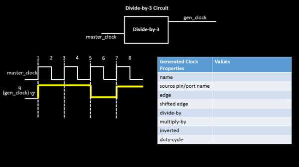
Let’s take a simple divide-by-3 circuit and below is how its waveform at output will look like (assuming a non-50% duty cycle). The output clock period is 3 times the input clock period and hence, frequency is divided-by-3. (It would be a great idea to show the interiors of divide-by-3 circuit. Stay with me and I will do that in following posts)
So, now, if we need to write this gen_clock definition, its simple. Just fill out the table and below is what we get
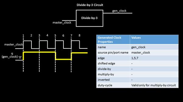
This shows a perfect usage of ‘edge’ option. For circuits producing a clock waveform which has non-50% duty cycle, the edge option can be very well used to define an output clock and can also be propagated throughout the circuit. It just says, that 1st rise edge of gen_clock arrives at 1st edge of master_clock, 1st fall edge of get_clock arrives at 5th edge of master_clock and 2nd rise edge (which completes 1 clock cycle) arrives at 7th edge of master_clock
Pay attention to the words above. I am using ‘rise’ and ‘fall’ words for defining gen_clock (as these words are the one’s that completes one clock cycle) and I am using just the word ‘edge’ for master_clock and ‘edge’ can be either rise or fall, doesn’t matter from gen_clock definition perspective
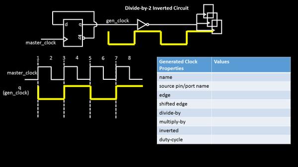
Now, to explore other options of this table, let’s look into another circuit specification, where output is inverted and divide-by-2 of input waveform.
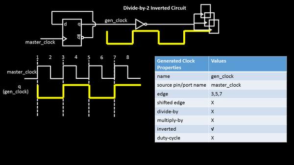
There are 2 ways to define this clock.
- Just use the options divide-by 2 and ‘inverted’, while put an ‘X’ for other ones, where ‘X’ means, say, ‘not needed’ This completes the definition of inverted, divide-by-2 gen clock OR….(sentence completed after below image)
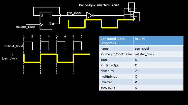
2. ….(sentence continued from above image), use the edge based definition, where gen_clock edge position with respect to master clock is clearly stated as below
So, what if the table is given to you and you have to derive or plot the output waveform? What if the gen_clock edges do not align with master clock edges (i.e. if one of gen_clock edge falls in between say edges ‘2’ and ‘3’ of master clock)? How do we define these complicated gen_clocks. Well I hate the word complicated and my job is to break and make it simple and more simple
As the Chinese say, “He who asks a question, remains a fool for five minutes. He who does not ask, remains a fool forever” —
So keep those questions coming.
