Overview
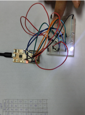
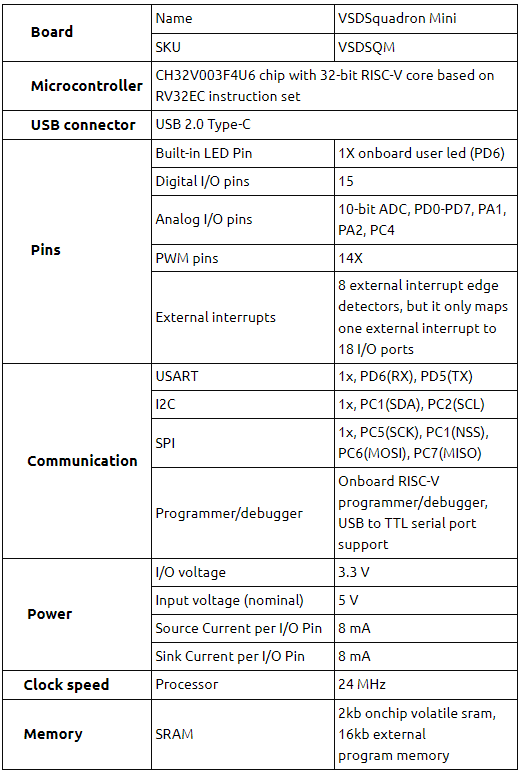
This project demonstrates the implementation of a binary to Gray code converter using the VSDSquadron Mini. The goal is to take a 3-bit binary input from the user and convert it into a 3-bit Gray code output. This conversion is crucial in digital systems for minimizing errors in signal processing and data transmission. The project utilizes the VSDSquadron Mini’s GPIO capabilities and programming flexibility, showcasing an application of RISC-V processors in digital logic design.
Components Required to Build Binary to Gray Code converter
- VSDSquadron Mini
- LEDs (for output indication)
- Buttons (for binary input)
- Breadboard
- Jumper Wires
- PlatformIO
- VS Code for software development
Circuit Connection for Binary to Gray Code converter
1. LED’s Connection
- LED1 (Gray Code Bit 2) connected to GPIO Pin_0
- LED2 (Gray Code Bit 1) connected to GPIO Pin_2
- LED3 (Gray Code Bit 0) connected to GPIO Pin_3
2. Buttons Connection
- Button1 (Binary Input Bit 2) connected to GPIO Pin_4
- Button2 (Binary Input Bit 1) connected to GPIO Pin_5
- Button3 (Binary Input Bit 0) connected to GPIO Pin_6
How to Program
1. Start by including the necessary header files for the CH32V003 RISC-V processor
#include <ch32v00x.h>

#include <debug.h>
2. Implement the XOR function to perform bit-wise XOR operation needed for Gray code conversion.
int xor(int bit1, int bit2)
{

 return bit1 ^ bit2;

}
3. Configure the GPIO pins for reading the binary input and setting the Gray code output.
void GPIO_Config(void)
{

 // Configuration code for input and output GPIO pins

}
4. In the main function, continuously read the binary input from the buttons, convert it to Gray code using the XOR function, and display the result on the LEDs.
int main(void)
{

 // Main loop for binary to Gray code conversion and output display

}
Working
The converter operates by reading a 3-bit binary input through buttons, applying the binary to Gray code conversion formula, and displaying the resulting Gray code on LEDs. The conversion process involves exclusive OR operations to calculate each bit of the Gray code based on the input binary bits. This project provides a practical example of digital logic design using a RISC-V based development board.
Code
The code includes functions for GPIO configuration, the XOR logic for binary to Gray conversion, and the main loop for continuous operation. The project demonstrates handling input from GPIO pins, processing the data according to digital logic principles, and outputting the result through GPIO pins.
Detailed Project Report
https://drive.google.com/file/d/12cUG2bix1QhM1PYhgAilZgHISEdt_eQs/view
Github Repo
https://github.com/kushaanbhat/somaiya-riscv
Application Video
Related Posts:
- Making a Game Console Using VSDSquadron Mini
- The Future of Chip Design: The Next Generation is…
- COLORIMETER
- RISC-V Mini Game Console
- LiFi Lock - An authentication system using LiFi…
- Real Time Implementation of BitNetMCU
- Shape Tomorrow’s Technology Today: ELCIA Hackathon…
- Soldiers Health Monitoring and GPS Tracking System
- Home safety system
- Smart Plant Care using the VSD_Squadron-MINI-BOARD


