Overview
This project involves implementing a 2-bit array multiplier using the VSDSquadron Mini, a RISC-V based SoC development kit. An array multiplier is a crucial digital circuit in digital electronics, widely used for multiplying two binary numbers. The 2-bit array multiplier specifically multiplies two 2-bit numbers to produce a 4-bit result. This project demonstrates the practical application of digital logic and RISC-V architecture in executing arithmetic operations, highlighting the process of reading binary inputs, executing multiplication through digital logic gates simulated by programming, and displaying the output.
Components Required
- VSDSquadron Mini
- Input Buttons for binary numbers
- LEDs for displaying output
- Breadboard
- Jumper Wires
- PlatformIO
- VS Code for software development
Hardware Connections
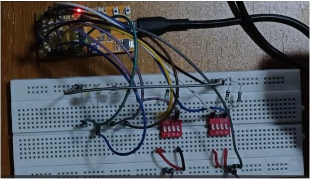
- Inputs : Two sets of 2-bit inputs are connected to the GPIO pins of the VSDSquadron Mini for the binary numbers to be multiplied.
- Outputs : Four LEDs connected to different GPIO pins display the 4-bit multiplication result.
- The specific GPIO pins used for inputs and outputs should be configured according to the project code, ensuring correct data flow and output display.
How to Program
1. Include Header Files : Start by including the necessary header files that provide access to the VSDSquadron Mini’s functionalities.
#include <ch32v00x.h>

#include <debug.h>
2. Define Logic Gate Functions : Implement functions to simulate digital logic gates. For a 2-bit array multiplier, functions for AND and XOR gates are crucial as they simulate the generation of partial products and their addition.
int and_gate(int bit1, int bit2) {

return bit1 & bit2;

}

int xor_gate(int bit1, int bit2) {

return bit1 ^ bit2;

}
3. Configure GPIO Pins : Set up GPIO pins for reading inputs from buttons and displaying the output on LEDs. This involves configuring the pins as input or output, setting the pull-up/pull-down resistors for input pins, and specifying the speed for output pins.
void GPIO_Config(void) {

// Example configuration for an input pin

GPIO_InitTypeDef GPIO_InitStructure;

RCC_APB2PeriphClockCmd(RCC_APB2Periph_GPIOD, ENABLE);

GPIO_InitStructure.GPIO_Pin = GPIO_Pin_3; // Input pin

GPIO_InitStructure.GPIO_Mode = GPIO_Mode_IPU; // Pull-up input

GPIO_Init(GPIOD, &GPIO_InitStructure);

// Example configuration for an output pin

GPIO_InitStructure.GPIO_Pin = GPIO_Pin_2; // Output pin

GPIO_InitStructure.GPIO_Mode = GPIO_Mode_Out_PP; // Push-pull output

GPIO_InitStructure.GPIO_Speed = GPIO_Speed_50MHz;

GPIO_Init(GPIOD, &GPIO_InitStructure);

}
4. Main Function : The main logic where inputs are read, the multiplication is performed, and results are displayed. This part involves reading the state of input pins, computing the multiplication using AND and XOR operations, and setting the output pins accordingly to display the result.
int main(void) {

SystemCoreClockUpdate(); // Update system clock

NVIC_PriorityGroupConfig(NVIC_PriorityGroup_2); // Configure NVIC

Delay_Init(); // Initialize delay functions

GPIO_Config(); // Configure GPIO

while (1) {

// Assume GPIO_ReadInputDataBit and GPIO_WriteBit are utility functions

// to read input states and write output states, respectively.

// Reading input bits

uint8_t a0 = GPIO_ReadInputDataBit(GPIOD, GPIO_Pin_3);

uint8_t a1 = GPIO_ReadInputDataBit(GPIOD, GPIO_Pin_4);

uint8_t b0 = GPIO_ReadInputDataBit(GPIOC, GPIO_Pin_3);

uint8_t b1 = GPIO_ReadInputDataBit(GPIOC, GPIO_Pin_4);

// Computing partial products

uint8_t p0 = and_gate(a0, b0);

uint8_t p1 = xor_gate(and_gate(a0, b1), and_gate(a1, b0));

// Additional operations for p2, p3 as per the 2-bit multiplication logic

// Displaying results on LEDs

GPIO_WriteBit(GPIOD, GPIO_Pin_2, p0 ? SET : RESET);

// Additional GPIO_WriteBit calls to display p1, p2, p3

}

}
This structured approach gives a clear overview of setting up the project, including initializing the system, configuring GPIO pins, defining logic operations, and implementing the core functionality to simulate a 2-bit array multiplier using the VSDSquadron Mini.
Working
The 2-bit array multiplier works by reading two 2-bit binary numbers from the input buttons, calculating the partial products, shifting, and adding them as per the binary multiplication algorithm. The final 4-bit product is displayed using LEDs. This involves bitwise AND operations for generating partial products, bitwise XOR for addition, and logical shifts to align the bits corr
Code
The code is structured to include initialization, GPIO configuration for inputs and outputs, logic gate function definitions, and a loop where the multiplication process is continuously executed. Inputs are read from GPIO pins, processed to calculate the multiplication result, and the result is displayed on LEDs.
Detailed Project Report
https://drive.google.com/file/d/1FeMuWhDoe-iyqMA1rNgYxU5zoSzB0ILD/view?usp=drivesdk
GitHub Repository
https://github.com/Vivekchoudhary2/somaiya-riscv


