Overview
This project is a straightforward demonstration aimed at testing I2C communication on the VSDSquadron Mini using the PlatformIO framework. It showcases the device operating in either master or slave mode within an I2C setup to transmit or receive a predefined sequence of bytes.
Components Required
- VSDSquadron Mini
- I2C compatible devices or another VSDSquadron Mini set as the counterpart (Master/Slave)
- USB to UART converter for programming and power
- Jumper wires for connections
Hardware Connections
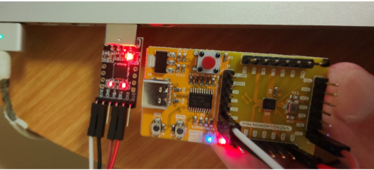
Ensure correct wiring between the VSDSquadron Mini and the I2C device as follows:
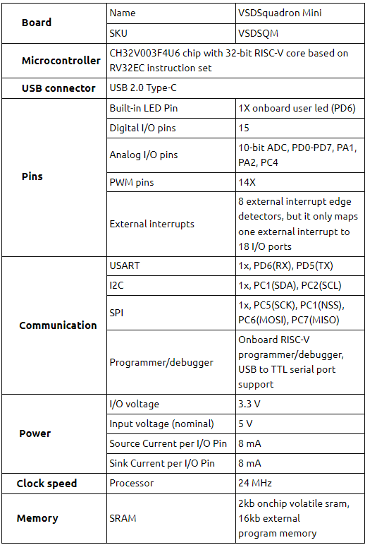
- PC1 (SDA) to SDA
- PC2 (SCL) to SCL
- GND to Ground
- 3.3V to 3.3V
How to Program
- Install PlatformIO Core : Begin by installing PlatformIO Core on your system according to the official PlatformIO documentation.
- Project Commands :
- Build the project: $ pio run
- Upload the firmware: $ pio run –target upload
- Clean build files: $ pio run –target clean
API Reference
- USART_Printf_Init() : Initializes the USART peripheral for debugging.
- Delay_Ms() : Creates a delay for a specified number of milliseconds.
- USART_SendData() : Sends data through the USART peripheral.
- USART_ReceiveData() : Retrieves the most recent data received by the USART peripheral.
- USART_GetFlagStatus() : Checks the status of specified USART flags.
Code Snippet
Below is a simplified excerpt of the main code highlighting initialization and I2C data transmission logic:
The following is an enhanced and comprehensive code snippet that includes both the initialization function and the main function logic for I2C communication in both host (master) and slave modes:
#include "debug.h"

/* I2C Mode Definition */

#define HOST_MODE 0

#define SLAVE_MODE 1

/* I2C Communication Mode Selection */

#define I2C_MODE HOST_MODE

/* Global define */

#define Size 6

#define RXAdderss 0x02

#define TxAdderss 0x02

/* Global Variable */

u8 TxData[Size] = {0x01, 0x02, 0x03, 0x04, 0x05, 0x06};

u8 RxData[5][Size];

void IIC_Init(u32 bound, u16 address) {

GPIO_InitTypeDef GPIO_InitStructure;

I2C_InitTypeDef I2C_InitTSturcture;

RCC_APB2PeriphClockCmd(RCC_APB2Periph_GPIOC | RCC_APB2Periph_AFIO, ENABLE);

RCC_APB1PeriphClockCmd(RCC_APB1Periph_I2C1, ENABLE);

// SCL Pin Configuration

GPIO_InitStructure.GPIO_Pin = GPIO_Pin_2;

GPIO_InitStructure.GPIO_Mode = GPIO_Mode_AF_OD;

GPIO_InitStructure.GPIO_Speed = GPIO_Speed_50MHz;

GPIO_Init(GPIOC, &GPIO_InitStructure);

// SDA Pin Configuration

GPIO_InitStructure.GPIO_Pin = GPIO_Pin_1;

GPIO_Init(GPIOC, &GPIO_InitStructure);

// I2C Peripheral Configuration

I2C_InitTSturcture.I2C_ClockSpeed = bound;

I2C_InitTSturcture.I2C_Mode = I2C_Mode_I2C;

I2C_InitTSturcture.I2C_DutyCycle = I2C_DutyCycle_2;

I2C_InitTSturcture.I2C_OwnAddress1 = address;

I2C_InitTSturcture.I2C_Ack = I2C_Ack_Enable;

I2C_InitTSturcture.I2C_AcknowledgedAddress = I2C_AcknowledgedAddress_7bit;

I2C_Init(I2C1, &I2C_InitTSturcture);

I2C_Cmd(I2C1, ENABLE);

}

int main(void) {

SystemCoreClockUpdate();

Delay_Init();

USART_Printf_Init(460800);

printf("SystemClk:%d\r\n", SystemCoreClock);

printf("IIC Host mode\r\n");

IIC_Init(80000, TxAdderss);

#if (I2C_MODE == HOST_MODE)

// Host Mode Operations: Master sends data to Slave

for (int j = 0; j < 5; j++) {

// I2C Master Transmit Sequence

}

#elif (I2C_MODE == SLAVE_MODE)

// Slave Mode Operations: Slave receives data from Master

for (int p = 0; p < 5; p++) {

// I2C Slave Receive Sequence

}

#endif

while (1);

}
Explanation
- IIC_Init Function : Initializes the I2C peripheral, including setting up the GPIO pins for I2C functions (SCL and SDA) and configuring I2C parameters such as clock speed, addressing mode, and duty cycle.
- Main Function :
- System Initialization: Updates the system core clock and initializes delay functions and USART for debugging.
- I2C Mode Selection: The code can operate in either HOST_MODE or SLAVE_MODE, determined by the I2C_MODE macro. This allows for flexible testing of both master and slave operations.
- Host Mode Operations: If in HOST_MODE, the device is configured as an I2C master, initiating communication with a slave device to transmit a series of data packets.
- Slave Mode Operations: If in SLAVE_MODE, the device acts as an I2C slave, ready to receive data packets from an I2C master.
Note
This example illustrates a framework for initiating I2C communication in either master or slave mode but does not include the specific implementation details for data transmission and reception sequences (// I2C Master Transmit Sequence and // I2C Slave Receive Sequence). Those sequences require the implementation of I2C API functions such as I2C_GenerateSTART, I2C_SendData, I2C_ReceiveData, etc., which should be tailored.
Working Principle
The code demonstrates the VSDSquadron Mini’s capability to engage in I2C communication either as a master, sending a predefined set of data to a slave device, or as a slave, receiving data from a master. It utilizes PlatformIO for building and uploading the firmware, facilitating easy testing and deployment of I2C-based applications.
Caution
Ensure all devices in the I2C setup are compatible with 3.3V logic levels to prevent damage. The common ground must be established between the VSDSquadron Mini and other I2C devices to ensure reliable communication.
Detailed Project report
https://github.com/davidbroughsmyth/vsdsquadron-mini-research/tree/main/I2C_poc
Related Posts:
- Shape Tomorrow’s Technology Today: ELCIA Hackathon…
- Bluetooth automated smart access
- Soldiers Health Monitoring and GPS Tracking System
- PARKinSENSE
- Water level monitoring and control in water tank
- COLORIMETER
- The Future of Chip Design: The Next Generation is…
- Secure Saiyan
- RISC-V Mini Game Console
- Real Time Implementation of BitNetMCU


