Introduction
The “Smart Plant Care” project is an innovative IoT solution aimed at optimizing plant growth by monitoring essential environmental parameters. By leveraging advanced sensors and microcontrollers, our system measures the moisture content of the soil, temperature, and humidity. This information is crucial for maintaining optimal plant health and growth. The project addresses the increasing need for efficient plant care in both residential and agricultural settings, ensuring that plants receive the right amount of water at the right time.
Overview
The Smart Plant Care system operates through a network of interconnected components that work together to provide real-time monitoring and automated watering solutions. The user can remotely monitor the plant’s environment and adjust the soil moisture threshold via a WiFi-connected interface. When the soil moisture level falls below the set threshold, the system automatically activates a water pump to deliver the necessary amount of water to the plant. This process helps in conserving water and ensuring that the plant remains healthy.
User Flow
- Data Collection: Sensors measure soil moisture levels, temperature, and humidity.
- Data Transmission: The CH32V003F4U6 microcontroller collects data from the sensors and sends it to the ESP-01S ESP8266 WiFi Module.
- Remote Monitoring: The ESP8266 transmits the data over WiFi, allowing the user to monitor real-time conditions through a web interface.
- Threshold Setting: Users can set and adjust the soil moisture threshold via the web interface.
- Automated Watering: When soil moisture falls below the threshold, the system activates the water pump to irrigate the plant.
How It Works
- Sensor Data Acquisition:
- The soil moisture sensor checks the soil’s moisture level.
- The DHT11 sensor measures ambient temperature and humidity.
- Data Processing:
- The CH32V003F4U6 microcontroller processes the sensor data and determines if the soil moisture is below the user-defined threshold.
- It also monitors temperature and humidity data.
- Data Transmission:
- Processed data is sent to the ESP-01S ESP8266 WiFi module, which transmits it to the user’s web interface for real-time monitoring.
- Automated Response:
- If the soil moisture is below the threshold, the microcontroller activates the water pump through a switch to irrigate the plant.
- User Interaction:
- The user can monitor real-time data, set moisture thresholds, and control the watering system remotely via the web interface.
Components Required
- CH32V003F4U6 Microcontroller: Acts as the central processing unit, managing sensor data and system operations.
- ESP-01S ESP8266 WiFi Module: Facilitates wireless communication, allowing remote data monitoring and control.
- Soil Moisture Sensor Module: Detects the moisture content in the soil.
- DHT11 Humidity and Temperature Sensor: Measures ambient temperature and humidity.
- Water Pump: Provides irrigation to the plant when needed.
- Relay Module: Helps to control high-power pump with low-power signals.
- Switch: Manages the on/off states of the water pump.
This project aims to create a reliable and efficient system for plant care, suitable for both residential and agricultural use. By leveraging IoT technology, Smart Plant Care ensures plants receive the optimal amount of water and thrive in their environment.
Circuit Connection Diagram
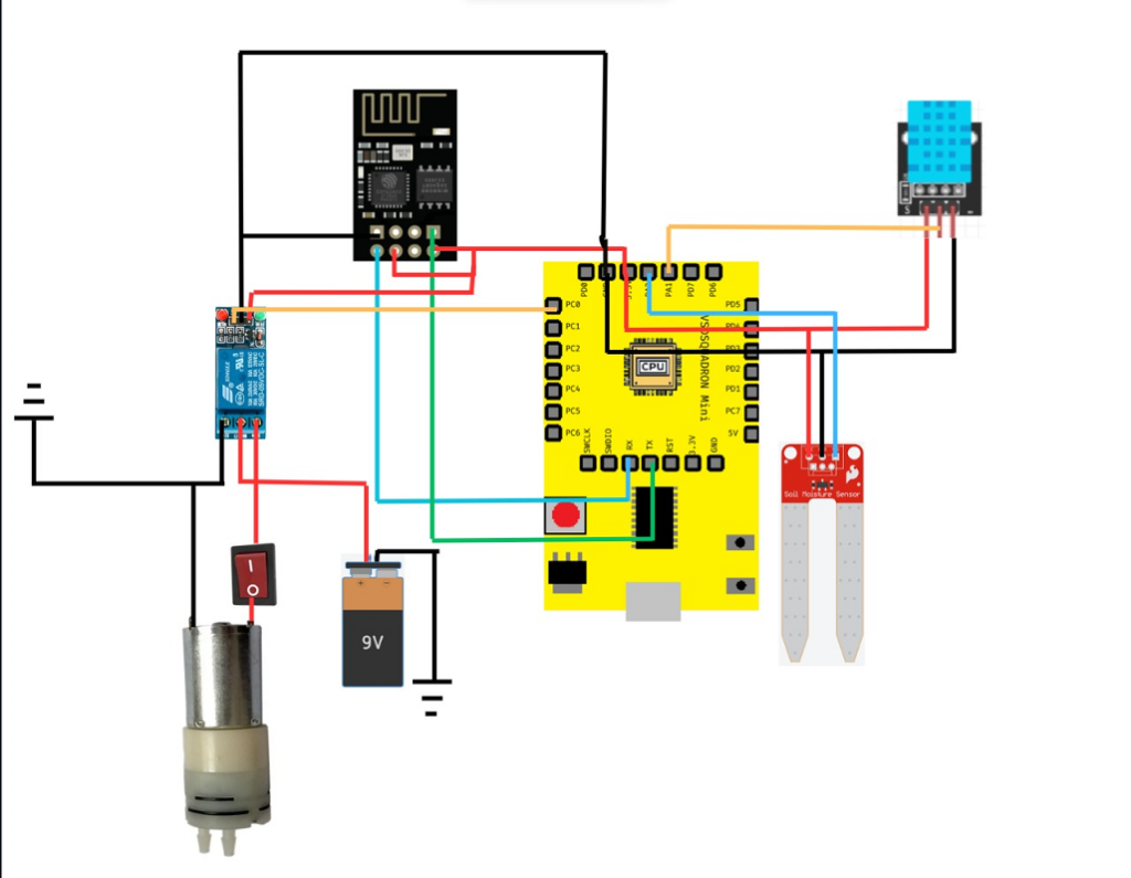
Table For Pin Configuration
For Soil Moisture senosor
| Soil Moisture sensor | VSDsquadron |
|---|---|
| VCC | 3.3V |
| GND | GND |
| SIG | PA2 |
For Relay module
| Relay | VSDsquadron | external battery | Motor |
|---|---|---|---|
| VCC | 3.3V | – | – |
| GND | GND | – | – |
| IN | PC0 | – | – |
| common contact | – | 9V | – |
| Normally Closed | – | – | – |
| Normally Open | – | – | VCC |
For ESP 01S 8266 wifi module
| ESP 8266 | VSDsquadron |
|---|---|
| VCC | 3.3V |
| CH_EN | 3.3V |
| GND | GND |
| U0RXD | TX(PD5) |
| U0TXD | RX(PD6) |
Working Code
Code for VSD squadron mini for getting the moisture content of the soil and communicating with the wifi module
#include <ch32v00x.h>
#include <debug.h>

/* Macros for ADC Pin and Port */
#define ANALOG1_PIN     GPIO_Pin_4
#define ANALOG1_PORT    GPIOD

#define MOTOR_PIN     GPIO_Pin_2
//#define MOTOR_PORT   GPIOD

/* Global Variables */
volatile uint8_t adcFlag = 0;
#define LED_PIN GPIO_Pin_3 // Assuming the LED is connected to GPIO pin 3 (D3 on port D)

/* Function Prototypes */
void NMI_Handler(void) __attribute__((interrupt("WCH-Interrupt-fast")));
void HardFault_Handler(void) __attribute__((interrupt("WCH-Interrupt-fast")));
void ADC1_IRQHandler(void) __attribute__((interrupt("WCH-Interrupt-fast")));
void Delay_Init(void);
void Delay_Ms(uint32_t n);
void ADCConfig(void);
void USARTx_CFG(void);
void USART_SendString(char* str);

void ADCConfig(void) {
    ADC_InitTypeDef ADC_InitStructure = {0};
    GPIO_InitTypeDef GPIO_InitStructure = {0};
    NVIC_InitTypeDef NVIC_InitStructure = {0};

    RCC_APB2PeriphClockCmd(RCC_APB2Periph_GPIOD, ENABLE);
    RCC_APB2PeriphClockCmd(RCC_APB2Periph_ADC1, ENABLE);
    RCC_ADCCLKConfig(RCC_PCLK2_Div8);

    GPIO_InitStructure.GPIO_Pin = ANALOG1_PIN;
    GPIO_InitStructure.GPIO_Mode = GPIO_Mode_AIN;
    GPIO_Init(ANALOG1_PORT, &GPIO_InitStructure);

    ADC_DeInit(ADC1);
    ADC_InitStructure.ADC_Mode = ADC_Mode_Independent;
    ADC_InitStructure.ADC_ScanConvMode = DISABLE;
    ADC_InitStructure.ADC_ContinuousConvMode = DISABLE;
    ADC_InitStructure.ADC_ExternalTrigConv = ADC_ExternalTrigInjecConv_None;
    ADC_InitStructure.ADC_DataAlign = ADC_DataAlign_Right;
    ADC_InitStructure.ADC_NbrOfChannel = 1;
    ADC_Init(ADC1, &ADC_InitStructure);

    ADC_InjectedSequencerLengthConfig(ADC1, 1);
    ADC_InjectedChannelConfig(ADC1, ADC_Channel_7, 1, ADC_SampleTime_241Cycles);  // Increased sample time for stability
    ADC_ExternalTrigInjectedConvCmd(ADC1, DISABLE);

    NVIC_InitStructure.NVIC_IRQChannel = ADC_IRQn;
    NVIC_InitStructure.NVIC_IRQChannelPreemptionPriority = 2;
    NVIC_InitStructure.NVIC_IRQChannelSubPriority = 0;
    NVIC_InitStructure.NVIC_IRQChannelCmd = ENABLE;
    NVIC_Init(&NVIC_InitStructure);

    ADC_Calibration_Vol(ADC1, ADC_CALVOL_50PERCENT);
    ADC_ITConfig(ADC1, ADC_IT_JEOC, ENABLE);
    ADC_Cmd(ADC1, ENABLE);

    ADC_ResetCalibration(ADC1);
    while (ADC_GetResetCalibrationStatus(ADC1));

    ADC_StartCalibration(ADC1);
    while (ADC_GetCalibrationStatus(ADC1));
}

void USARTx_CFG(void) {
    GPIO_InitTypeDef GPIO_InitStructure = {0};
    USART_InitTypeDef USART_InitStructure = {0};

    RCC_APB2PeriphClockCmd(RCC_APB2Periph_GPIOD | RCC_APB2Periph_USART1, ENABLE);

    /* USART1 TX-->D.5   RX-->D.6 */
    GPIO_InitStructure.GPIO_Pin = GPIO_Pin_5;
    GPIO_InitStructure.GPIO_Speed = GPIO_Speed_50MHz;
    GPIO_InitStructure.GPIO_Mode = GPIO_Mode_AF_PP;
    GPIO_Init(GPIOD, &GPIO_InitStructure);
    GPIO_InitStructure.GPIO_Pin = GPIO_Pin_6;
    GPIO_InitStructure.GPIO_Mode = GPIO_Mode_IN_FLOATING;
    GPIO_Init(GPIOD, &GPIO_InitStructure);

    USART_InitStructure.USART_BaudRate = 115200;
    USART_InitStructure.USART_WordLength = USART_WordLength_8b;
    USART_InitStructure.USART_StopBits = USART_StopBits_1;
    USART_InitStructure.USART_Parity = USART_Parity_No;
    USART_InitStructure.USART_HardwareFlowControl = USART_HardwareFlowControl_None;
    USART_InitStructure.USART_Mode = USART_Mode_Tx | USART_Mode_Rx;

    USART_Init(USART1, &USART_InitStructure);
    USART_Cmd(USART1, ENABLE);
}

void USART_SendString(char* str) {
    while (*str) {
        USART_SendData(USART1, *str++);
        while (USART_GetFlagStatus(USART1, USART_FLAG_TXE) == RESET) {
            /* waiting for sending finish */
        }
    }
}

void ADC1_IRQHandler() {
    if (ADC_GetITStatus(ADC1, ADC_IT_JEOC) == SET) {
        adcFlag = 1;
        ADC_ClearITPendingBit(ADC1, ADC_IT_JEOC);
    }
}

void LED_Config(void) {
    GPIO_InitTypeDef GPIO_InitStructure;

    RCC_APB2PeriphClockCmd(RCC_APB2Periph_GPIOD, ENABLE);

    GPIO_InitStructure.GPIO_Pin = LED_PIN;
    GPIO_InitStructure.GPIO_Mode = GPIO_Mode_Out_PP; // Output push-pull
    GPIO_InitStructure.GPIO_Speed = GPIO_Speed_50MHz;
    GPIO_Init(GPIOD, &GPIO_InitStructure);

    GPIO_InitStructure.GPIO_Pin = MOTOR_PIN;
    GPIO_InitStructure.GPIO_Mode = GPIO_Mode_Out_PP; // Output push-pull
    GPIO_InitStructure.GPIO_Speed = GPIO_Speed_50MHz;
    GPIO_Init(GPIOD, &GPIO_InitStructure);

}


int main(void) {
    NVIC_PriorityGroupConfig(NVIC_PriorityGroup_2);
    SystemCoreClockUpdate();
    Delay_Init();
    USART_Printf_Init(115200);
    Delay_Ms(100); // give serial monitor time to open

    USARTx_CFG();
    ADCConfig();
    LED_Config();
    int accumulatedValue   = 0;

    while (1) {
        ADC_SoftwareStartInjectedConvCmd(ADC1, ENABLE);
        uint16_t adcAverage = 0;
        if (adcFlag == 1) {
            static uint32_t adcAccumulated = 0;
            static uint8_t sampleCount = 0;
            const uint8_t maxSamples = 100;
            while(sampleCount <= maxSamples)
            {
                uint16_t adcReading = ADC_GetInjectedConversionValue(ADC1, ADC_InjectedChannel_1);

                // Optional: Apply averaging filter to stabilize the readings
                // Adjust number of samples for averaging
                adcAccumulated += adcReading;
                sampleCount++;
            }


            if (sampleCount >= maxSamples) {
                adcAverage = adcAccumulated / maxSamples;
                adcAccumulated = 0;
                sampleCount = 0;

                printf("%d\n", adcAverage);
            }

            adcFlag = 0;

            accumulatedValue   = 0;
            int i = 0;
            while(1)
            {
                while (USART_GetFlagStatus(USART1, USART_FLAG_RXNE) == RESET) {

                }

                char receivedChar = USART_ReceiveData(USART1);

                if (receivedChar !='a' ) {

                    accumulatedValue = accumulatedValue * 10 + (receivedChar - '0');
                } else {

                    break;
                }
                i++;
            }

            if (accumulatedValue > adcAverage) {   // less water
                GPIO_SetBits(GPIOD, LED_PIN); // Turn on LED
                GPIO_SetBits(GPIOD, MOTOR_PIN);
            } else {
                GPIO_ResetBits(GPIOD, LED_PIN); // Turn off LED  // water ok
                GPIO_ResetBits(GPIOD, MOTOR_PIN);
            }
            Delay_Ms(10);
        }


    }
}

void NMI_Handler(void) {}
void HardFault_Handler(void) {
    while (1) {
    }
}
Code for ESP01-8266 wifi module for coummunation between the VSD squadron mini and the backend server
#include <ESP8266WiFi.h>
#include <ESP8266HTTPClient.h>
#include <ArduinoJson.h>

const char* ssid = "Redmi";
const char* password = "kafil1234";
const char* serverUrlPost = "http://13.234.21.117:8000/api/receive/"; // URL for POST requests
const char* serverUrlGet = "http://13.234.21.117:8000/api/send/"; // URL for GET requests

WiFiClient wifiClient;
HTTPClient http;

unsigned long lastSendTime = 0;
const unsigned long sendInterval = 1000;  // 5 seconds
unsigned long lastGetTime = 0;
const unsigned long getInterval = 1000;   // 5 seconds

void setup() {
  Serial.begin(115200); // Initialize serial communication at 115200 baud rate
  delay(1000); // Small delay to stabilize the Serial connection
  WiFi.begin(ssid, password);

  while (WiFi.status() != WL_CONNECTED) {
    delay(500);
  }
}

void loop() {
  // Check if there's data available from the Arduino
  if (Serial.available() > 0) {
    String sensorData = Serial.readStringUntil('\n');
    sensorData.trim();

    while (millis() - lastSendTime < sendInterval) {
      delay(10); // small delay to avoid blocking other tasks
    }

    if (millis() - lastSendTime >= sendInterval) {
      if (WiFi.status() == WL_CONNECTED) {
        http.begin(wifiClient, serverUrlPost);
        http.addHeader("Content-Type", "application/json");

        // Create the JSON payload with the received string
        String postData = "{\"sensor_data\": \"" + sensorData + "\"}";

        int httpResponseCode = http.POST(postData);
        if (httpResponseCode > 0) {
          // Successfully sent
        } else {
          // Error on sending POST
        }
        http.end();
      } else {
        WiFi.begin(ssid, password);
        while (WiFi.status() != WL_CONNECTED) {
          delay(500);
        }
      }

      lastSendTime = millis();
    }
  }

  // Periodically send a GET request to the server to check for new data
  if (millis() - lastGetTime >= getInterval) {
    if (WiFi.status() == WL_CONNECTED) {
      http.begin(wifiClient, serverUrlGet);
      int httpResponseCode = http.GET();

      if (httpResponseCode > 0) {
        String response = http.getString();
        StaticJsonDocument<200> doc;
        DeserializationError error = deserializeJson(doc, response);

        if (!error) {
          if (doc.containsKey("value")) {
            int value = doc["value"];
            String output = String(value) + "a";
            Serial.print(output);
            //delay(10);
          }
        }
      }
      http.end();
    } else {
      WiFi.begin(ssid, password);
      while (WiFi.status() != WL_CONNECTED) {
        delay(500);
      }
    }

    lastGetTime = millis();
  }
}
Demo Video
Conclusion
The Smart Plant Care project integrates advanced IoT technology to provide an efficient and automated plant care system. By ensuring that plants receive the optimal amount of water based on real-time environmental data, this system enhances plant health and growth while conserving resources. With remote monitoring and control capabilities, users can manage their plants effortlessly, making Smart Plant Care a valuable tool for both hobbyists and professional growers.