Hello
This was exactly the feeling when I was told to do SPICE …. but you know what, after practically applying the concepts on real design, I felt, it wasn’t a new world. It was an extension towards accuracy, that guarantees your chip will not fail, in timing.
And, there it all started. I will be announcing my 5th course – “VLSI Academy – Circuit Design and SPICE simulations”, along with my existing 4 courses on Udemy, which covers right from Physical Design flow to clock tree synthesis to crosstalk to parasitic to timing.
SPICE comes exactly after these topics. Please follow this link to get details of my existing courses
So, let me brief you what exactly we are going to do in SPICE. To start with, below image clearly shows the basic flow of SPICE

The complex equations on the right side of the image, are not so complex, once I go through them in my way in the courses. These equations model a MOSFET, The left had side is one basic SPICE netlist (In the course, we will be looking into more complex one’s, but I will make sure, you go through the basic one’s first :))
When we provide both to SPICE engine, the output are some current waveforms (which eventually converts to a timing waveform, I will show you ‘how’ in the course, when I publish)
The below MOSFET device, with potential applied to drain terminal and source/substrate being grounded, can be represented by a circuit shown in right side of image. The nodes actually help us to create the SPICE deck or SPICE netlist. Stay with me to see ‘how’

Let’s write the SPICE deck for below MOSFET. The name is M1. The nodes are vdd, n1, 0 (follow the blue dots in the image) and the syntax is “mosfet_name drain gate source substrate“. When we write M1 vdd n1 0 0, it means drain is connected node vdd (blue dot), gate is connected to node n1, source and substrate is connected to node ‘0’. (since its ground, I named it ‘0’)

And, we do similar thing for resistor R1, input supply Vin, and main supply Vdd, like below

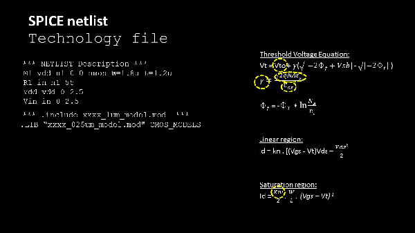
Netlist is ready. Now, we need to supply the model parameters, basically, the one’s encircled in yellow. Once we give that, SPICE engine internally has the equations or models that evaluates to give the output current values. The list is huge. Maybe, I will introduce them to you in the course

Once, you have them, pack all the technology related things, into a file, say, .mod file and point to that file, something like below. This helps maintenance of the files, as, we write SPICE netlist for complex gates.

Now, we provide circuit + technology file to SPICE engine along with below simulation commands …..(sentence continued after this image)


Does that interest you ? :). If yes, I will send you the link to my new course very soon. Be ready for another adventure. The above post, is just the beginning. I will be extrapolating it to getting accurate delay numbers, and how it helps improve timing accuracy, and many more …. Stay Hungry, stay tuned, stay excited 🙂
I believe “Learning should be a joy and full of excitement. It is the life’s greatest adventure; it is an illustrated excursion into the minds of noble and the learned“ – Taylor Caldwell
Thanks
Kunal


