Hey There,
Problem Statement –For hierarchical designs ~500k instance count, participants are expected to develop code which will build clock tree for a design which has close to ~50k sequential flip-flops using default routing rules
Inputs given for code development and testing:
- A text file in DEF format with clear definitions of core/die width, pad placement, pre-placed cells, power rings around core/pre-placed cells and other information unplaced/placed/fixed cell with locations of all flip-flops and combinational cells
- A netlist in Verilog format corresponding to above DEF
- Industry grade 180nm PDK’s (standard cells, memories, pads) LIB and LEF formats
Expected output:
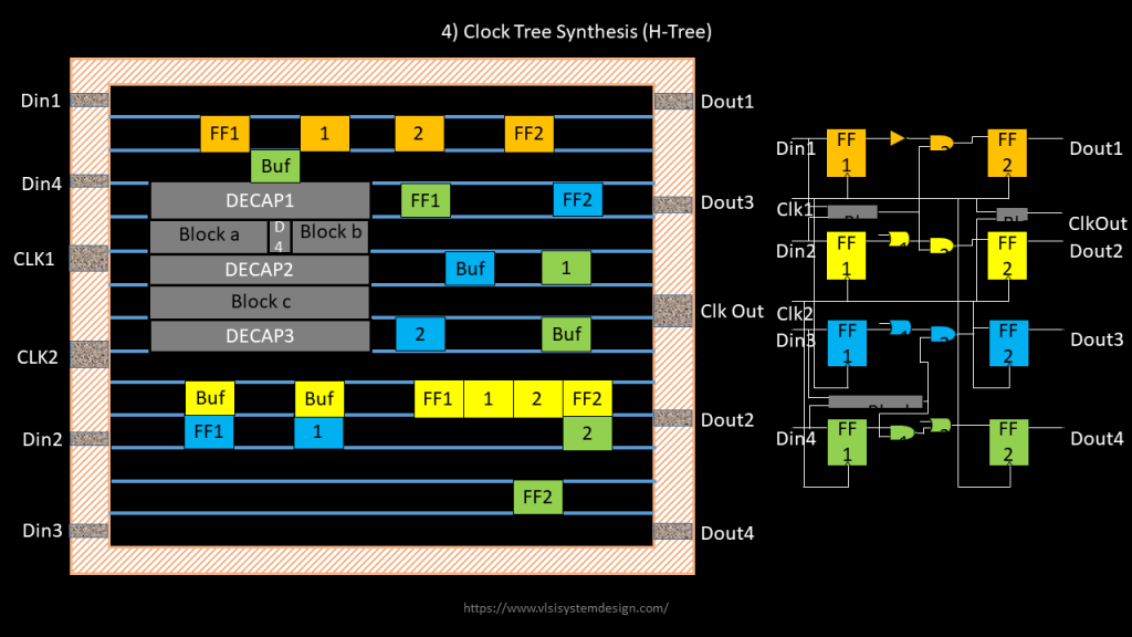
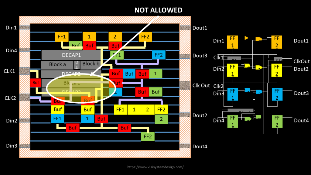
A text file in standard DEF format and Verilog netlist which has all information about inputs which were provided + information about clock tree buffer locations and clock route width (shown in below image)

Step 1) Find a way to parse input DEF file and verilog file, which has locations, co-ordinates, instance names, connectivity details and many more information of all instances that you see in Fig.2. It can be a command something like below
read_def <input_def_file>
read_verilog <input_verilog_file>
If the DEF file syntax is not in par with standard DEF syntax, issue an error message specifying line number where there is a syntax error. Same with verilog syntax

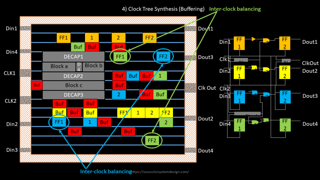
Step 2) Develop code (or command) to buffer the clock route using the list of balanced clock buffers provided based on estimated routing parasitics, so that there is no mismatch in rise and fall slew
It can be a command something like below.
buffer_clock_routes -list_of_buffers <list_of_buffers> -skew_target <skew_in_ps> -max_latency_target <max_latency_in_ps> -allow_inter_clock_balancing <true/false> -clock_name_list <list_of_clocks_to_be_buffered>
User can give command like below:
buffer_clock_routes -list_of_buffers “clkbuf1 clkbuf2 clkbuf4 clkbuf8” -skew_target 50ps -max_latency_target 10ns -allow_inter_clock_balancing true -clock_name “CLK1 CLK2”
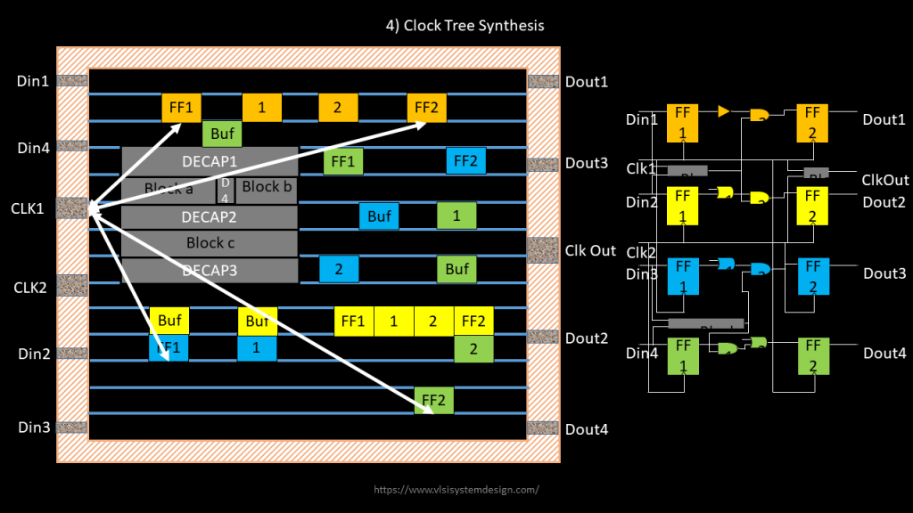
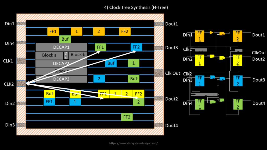
Step 3) Develop code (or command) which will identify and route all “related” flip-flops clock end-points (See below image for description) using default metal routing rules from tech lef. “Related” meaning, there is a path from FF1 to FF2 with CLK1 or CLK2
It can be a command something like below
route_clock_pins

Step 4) Routing over block is not allowed (see below image).
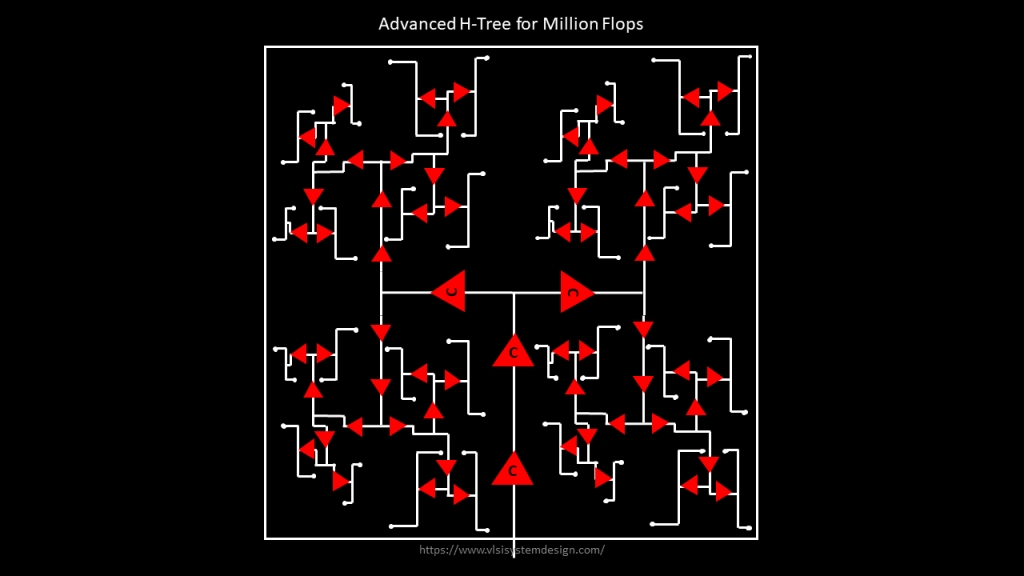
Step 5) For ~50k flops, the clock tree will something like below:
Step 6) Clock tree quality will be checked for skew(given in -target_skew), pulse width(default half of clock period), duty cycle(default 50%), latency(given in -max_latency_target), clock tree power and crosstalk coupling.
Terms and condition:
- You are free to use the source code of existing (and only) opensource tools like magic, qflow, graywolf, qrouter or any other
- Each line of your code needs to be open-sourced and documented


