Introduction
In an age where technology seamlessly integrates with our daily lives, the concept of a smart home has evolved from a futuristic vision to a tangible reality. Central to this transformation is the “Bluetooth Automated Smart Access” system, which embodies the blend of convenience, security, and innovation. Leveraging the capabilities of a VSD Squadron Mini board, a Bluetooth module, and a servo motor, this project offers practical solutions to everyday challenges, enhancing the way we interact with our living spaces.
Traditional methods of manual operation can be cumbersome, tiresome and inefficient. This technology eliminates such challenges by allowing users to manage various applications through their smartphones, reducing the need for physical interaction. Bluetooth automated smart access can be utilized in a wide range of applications, from controlling water taps to managing lighting and appliances, smart door and security applications and for enhancing efficiency and simplifying everyday tasks across diverse environments.
Overview
The project showcased here introduces an innovative solution utilising a servo motor, Bluetooth module, push-button, and onboard LED to control and monitor door access. Its functionality lies in its ability to initiate open-close mechanism upon delivering a bluetooth instruction message. When the bluetooth module receives an input, it triggers the VSD Squadron Mini to activate the Servo Motor, thereby initiating this mechanism. This technology-driven approach offers a hands-free and user-friendly solution for creating a secure and convenient tool access solution.
- Servo Motor (Pin PC6): Acts as the locking mechanism, controlled by the microcontroller.
- Bluetooth Module (Pins PD6, PD7, PC7, GND, 3.3V): Enables wireless communication between the system and a user’s smartphone for remote control and Bluetooth module’s State pin indicates connection status.
- Onboard LED (LED_BUILTIN): Displays the system status, indicating locked/unlocked states.
Users can control the device via their smartphone using Bluetooth. The onboard LED provides visual feedback, making the system user-friendly and reliable. This project exemplifies the practical application of IoT technology in home security and automation.
Components required with Bill of Materials
| Item | Quantity | Description | Links to Products |
|---|---|---|---|
| VSD Squadron Mini | 1 | Microcontroller board | VSD Squadron Mini |
| Servo Motor | 1 | Standard servo motor (e.g., SG90) | SG90 Servo Motor |
| Bluetooth HC-05 Module | 1 | Bluetooth module for serial communication | Bluetooth HC-05 |
| Jumper Wires | 1 set | Male-to-male and female-to-male jumper wires | Jumper Wires |
| Micro USB Cable | 1 | For programming and power supply | Micro USB Cable |
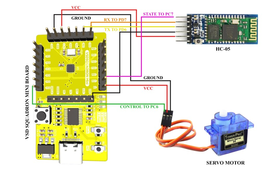
Table for Pin Connections
| Component | VSD Squadron Mini Pin | Description |
|---|---|---|
| Servo Signal | PC6 | Servo motor’s control signal pin |
| Servo VCC | 5V | Servo motor’s power supply |
| Servo GND | GND | Servo motor’s ground |
| Bluetooth RXD | PD6 | Bluetooth module’s RXD pin (connect directly to 3.3V logic) |
| Bluetooth TXD | PD7 | Bluetooth module’s TXD pin (connect directly to 5V logic) |
| Bluetooth GND | GND | Bluetooth module’s ground pin |
| Bluetooth VCC | 3.3V | Bluetooth module’s 3.3V pin (connect to microcontroller’s 3.3V output pin) |
| Bluetooth State | PC7 | Bluetooth module’s State pin (indicates connection status) |
| Onboard LED | LED_BUILTIN | Onboard LED for status indication |
Pinout Diagram
Working Code
// Define the pins using port names
#define MOTOR_PIN PC6 // Pin to which the servo motor is connected
#define BLUETOOTH_STATE_PIN PC7
#define LED_PIN LED_BUILTIN

#define BLUETOOTH_RX_PIN PD6  // Onboard RX pin
#define BLUETOOTH_TX_PIN PD7  // Onboard TX pin

bool doorLocked = true; // Flag to track the door lock state

// Function prototypes
void checkBluetooth();
void openDoor(int openDelay = 5000);
void closeDoor();
void lockDoor();
void setServoAngle(int angle);

void setup() {
  Serial.begin(9600);
  while (!Serial) {
    ; // Wait for serial port to connect. Needed for native USB port only
  }
  Serial.println("Smart Door System Initialized");

  pinMode(LED_PIN, OUTPUT);
  pinMode(BLUETOOTH_STATE_PIN, INPUT);

  pinMode(MOTOR_PIN, OUTPUT); // Set the motor pin as an output

  lockDoor(); // Lock the door initially
}

void loop() {
  // Check Bluetooth connection status
  if (digitalRead(BLUETOOTH_STATE_PIN) == HIGH) {
    checkBluetooth();
  } else {
    Serial.println("Bluetooth not connected");
    // Handle Bluetooth disconnection here (e.g., close the door)
    if (!doorLocked) {
      closeDoor();
    }
  }
}

void checkBluetooth() {
  if (Serial.available()) {
    char command = Serial.read();
    if (command == 'O') {  // Command to open the door
      openDoor();
    } else if (command == 'C') {  // Command to close the door
      closeDoor();
    }
  }
}

void openDoor(int openDelay) {
  Serial.println("Access Granted");
  digitalWrite(LED_PIN, HIGH);

  // Set PWM signal to open the door
  setServoAngle(90); // Assuming 90 degrees to open the door
  delay(openDelay); // Keep door open for the specified delay
  closeDoor();
}

void closeDoor() {
  Serial.println("Door Closing");
  digitalWrite(LED_PIN, LOW);

  // Set PWM signal to close the door
  setServoAngle(0); // Assuming 0 degrees to close the door
  doorLocked = true; // Update door lock state
}

void lockDoor() {
  doorLocked = true; // Update door lock state
  setServoAngle(0); // Initially lock the door by setting servo to 0 degrees
}

// Function to set the servo angle
void setServoAngle(int angle) {
  // Constants for the servo control
  const int minPulseWidth = 544;  // Minimum pulse width in microseconds
  const int maxPulseWidth = 2400; // Maximum pulse width in microseconds
  const int refreshInterval = 20000; // Refresh interval in microseconds (20 ms)

  // Map the angle to the pulse width
  int pulseWidth = map(angle, 0, 180, minPulseWidth, maxPulseWidth);

  // Generate the PWM signal on PC6
  digitalWrite(MOTOR_PIN, HIGH);
  delayMicroseconds(pulseWidth);
  digitalWrite(MOTOR_PIN, LOW);

  // Wait for the remainder of the refresh interval
  delayMicroseconds(refreshInterval - pulseWidth);
}
Demo Video
Application Video – Aqua Control System
Application Video – Railway Gate Modulator
Fault Injection
Fault injection is a testing technique used to evaluate the robustness and error-handling capabilities of a system by deliberately introducing faults or errors into it. The goal is to observe how the system behaves under fault conditions and to ensure that it can handle these situations gracefully. This technique is commonly used in software, hardware, and system testing to identify and fix potential weaknesses or vulnerabilities.
Objectives
- Identify Weaknesses: Detect vulnerabilities and weak points in the system that could lead to failures.
- Improve Robustness: Enhance the system’s ability to handle faults gracefully without crashing or producing incorrect results.
- Validate Error Handling: Ensure that error handling mechanisms and failover processes work correctly under fault conditions.
Challenges
Software Fault Injections
Simulate faultCondition
- “faultCondition” is a boolean flag initialized to false. It’s used to simulate a fault state in the system.
- The fault condition is triggered by a Bluetooth command within the checkBluetooth() function.
- Any single character command between ‘A’ and ‘Z’ (excluding ‘O’ and ‘C’) will set the faultCondition flag to true.
- This fault locks the door and skips the rest of the loop when detected, deeming any further inputs null and void.
Simulate rebootSystem
- “rebootSystem()” is a function that simulates a system reboot by resetting specific variables and calling setup() to reinitialize the system.
- The reboot is randomly triggered based on a timer within the loop() function.
- Every second (rebootCheckInterval), the system checks if a random event should trigger a reboot with a 10% chance.
Code for Software Fault Injection
// Define the pins using port names
#define MOTOR_PIN PC6 // Pin to which the servo motor is connected
#define BLUETOOTH_STATE_PIN PC7
#define LED_PIN LED_BUILTIN

#define BLUETOOTH_RX_PIN PD6  // Onboard RX pin
#define BLUETOOTH_TX_PIN PD7  // Onboard TX pin

bool doorLocked = true; // Flag to track the door lock state
bool faultCondition = false; // Flag to simulate a fault condition
unsigned long lastRebootCheck = 0; // Time of the last reboot check
const unsigned long rebootCheckInterval = 1000; // Check for reboot every 1 second

// Function prototypes
void checkBluetooth();
void openDoor(int openDelay = 1000);
void closeDoor();
void lockDoor();
void setServoAngle(int angle);
void rebootSystem();

void setup() {
  Serial.begin(9600);
  delay(100); // delay to ensure serial connection is established
  while (!Serial) {
    ; // Wait for serial port to connect. Needed for native USB port only
  }
  Serial.println("System Initialized");

  pinMode(LED_PIN, OUTPUT);
  pinMode(BLUETOOTH_STATE_PIN, INPUT);

  pinMode(MOTOR_PIN, OUTPUT); // Set the motor pin as an output

  randomSeed(analogRead(0)); // Initialize random seed

  lockDoor(); // Lock the door initially
}

void loop() {
  // Check for fault condition
  if (faultCondition) {
    Serial.println("Fault Detected! System is locking the door.");
    lockDoor(); // Lock the door immediately
    return; // Skip the rest of the loop
  }

  // Check Bluetooth connection status
  if (digitalRead(BLUETOOTH_STATE_PIN) == HIGH) {
    checkBluetooth();
  } else {
    Serial.println("Bluetooth not connected");
    // Handle Bluetooth disconnection here (e.g., close the door)
    if (!doorLocked) {
      closeDoor();
    }
  }

  // Check if it's time to randomly reboot
  if (millis() - lastRebootCheck > rebootCheckInterval) {
    lastRebootCheck = millis();
    if (random(0, 100) < 10) { // 10% chance to reboot
      Serial.println("Random reboot triggered!");
      rebootSystem();
    }
  }
}

void checkBluetooth() {
  if (Serial.available()) {
    char command = Serial.read();
    if (command == 'O') {  // Command to open the door
      openDoor();
    } else if (command == 'C') {  // Command to close the door
      closeDoor();
    } else if ((command >= 'A' && command <= 'Z') && command != 'O' && command != 'C') {  // Command to simulate a fault
      faultCondition = true;
      Serial.println("Fault simulation command received");
    }
  }
}

void openDoor(int openDelay) {
  Serial.println("Access Granted");
  digitalWrite(LED_PIN, HIGH);

  // Set PWM signal to open the door
  setServoAngle(90); // Assuming 90 degrees to open the door
  delay(openDelay); // Keep door open for the specified delay
}

void closeDoor() {
  Serial.println("Door Closing");
  digitalWrite(LED_PIN, LOW);

  // Set PWM signal to close the door
  setServoAngle(0); // Assuming 0 degrees to close the door
  doorLocked = true; // Update door lock state
}

void lockDoor() {
  doorLocked = true; // Update door lock state
  setServoAngle(0); // Initially lock the door by setting servo to 0 degrees
}

// Function to set the servo angle
void setServoAngle(int angle) {
  // Constants for the servo control
  const int minPulseWidth = 544;  // Minimum pulse width in microseconds
  const int maxPulseWidth = 2400; // Maximum pulse width in microseconds
  const int refreshInterval = 20000; // Refresh interval in microseconds (20 ms)

  // Map the angle to the pulse width
  int pulseWidth = map(angle, 0, 180, minPulseWidth, maxPulseWidth);

  // Generate the PWM signal on PC6
  digitalWrite(MOTOR_PIN, HIGH);
  delayMicroseconds(pulseWidth);
  digitalWrite(MOTOR_PIN, LOW);

  // Wait for the remainder of the refresh interval
  delayMicroseconds(refreshInterval - pulseWidth);
}

void rebootSystem() {
  // Simulate a system reboot by resetting variables and re-initializing
  Serial.println("Rebooting system...");
  doorLocked = true;
  faultCondition = false;
  lastRebootCheck = millis();

  setup(); // Call setup to re-initialize the system
}
Software Fault Protection
- Authorization: Added a verifyAuthorization function that prompts the user to enter an authorization code before critical commands are processed.
- Debounce Protection: Added a debounceProtection function to ensure commands aren’t processed too frequently.
- Scheduled Reboots: Reboots the system at regular intervals to prevent long-term instability.
- Reboot System: Resets critical variables and simulates a system reboot at predetermined intervals based on the loopCounter.
These protections ensure that only authorized users can issue critical commands, and that these commands can’t be spammed to disrupt the system.
Code for Software Fault Protection
// Define the pins using port names
#define MOTOR_PIN PC6 // Pin to which the servo motor is connected
#define BLUETOOTH_STATE_PIN PC7
#define LED_PIN LED_BUILTIN

#define BLUETOOTH_RX_PIN PD6  // Onboard RX pin
#define BLUETOOTH_TX_PIN PD7  // Onboard TX pin

bool doorLocked = true; // Flag to track the door lock state
bool faultCondition = false; // Flag to simulate a fault condition
unsigned long lastRebootTime = 0; // Time of the last reboot
const unsigned long rebootInterval = 60000; // Reboot every 60 seconds

// Counter for controlling reboots
unsigned long loopCounter = 0;
const unsigned long rebootThreshold = 6000; // Reboot after 6000 loops

const String authorizedCode = "OK"; // Example authorization code
bool authorized = false; // Flag to indicate if the user is authorized
unsigned long lastCommandTime = 0; // Time of the last received command
const unsigned long commandInterval = 5000; // Minimum interval between commands in milliseconds

// Function prototypes
void checkBluetooth();
void openDoor(int openDelay = 1000);
void closeDoor();
void lockDoor();
void setServoAngle(int angle);
void rebootSystem();
bool verifyAuthorization(String command);
bool debounceProtection();

void setup() {
  Serial.begin(9600);
  delay(100); // delay to ensure serial connection is established
  while (!Serial) {
    ; // Wait for serial port to connect. Needed for native USB port only
  }
  Serial.println("System Initialized");

  pinMode(LED_PIN, OUTPUT);
  pinMode(BLUETOOTH_STATE_PIN, INPUT);

  pinMode(MOTOR_PIN, OUTPUT); // Set the motor pin as an output

  randomSeed(analogRead(0)); // Initialize random seed

  // Initialize the last reboot time
  lastRebootTime = millis();

  lockDoor(); // Lock the door initially
}

void loop() {
  // Increment loop counter
  loopCounter++;

  // Check for fault condition
  if (faultCondition) {
    Serial.println("Fault Detected! System is locking the door.");
    lockDoor(); // Lock the door immediately
    return; // Skip the rest of the loop
  }

  // Check Bluetooth connection status
  if (digitalRead(BLUETOOTH_STATE_PIN) == HIGH) {
    checkBluetooth();
  } else {
    Serial.println("Bluetooth not connected");
    // Handle Bluetooth disconnection here (e.g., close the door)
    if (!doorLocked) {
      closeDoor();
    }
  }

  // Check if it's time to reboot based on loop counter
  if (loopCounter >= rebootThreshold) {
    Serial.println("Rebooting system...");
    rebootSystem();
  }
}

void checkBluetooth() {
  if (Serial.available()) {
    String command = Serial.readString();
    command.trim(); // Remove any leading/trailing whitespace

    if (!authorized) {
      if (verifyAuthorization(command)) {
        authorized = true;
        Serial.println("Authorization successful.");
      } else {
        Serial.println("Unauthorized command attempt.");
      }
    } else {
      if ((command == "O" || command == "C" || (command >= "A" && command <= "Z")) && debounceProtection()) {
        if (command == "O") {  // Command to open the door
          openDoor();
        } else if (command == "C") {  // Command to close the door
          closeDoor();
        } else {  // Command to simulate a fault
          faultCondition = true;
          Serial.println("Fault simulation command received");
        }
        authorized = false; // Reset authorization after a command is executed
      }
    }
  }
}

void openDoor(int openDelay) {
  Serial.println("Access Granted");
  digitalWrite(LED_PIN, HIGH);
  // Set PWM signal to open the door
  setServoAngle(90); // Assuming 90 degrees to open the door
}

void closeDoor() {
  Serial.println("Door Closing");
  digitalWrite(LED_PIN, LOW);
  // Set PWM signal to close the door
  setServoAngle(0); // Assuming 0 degrees to close the door
  doorLocked = true; // Update door lock state
}

void lockDoor() {
  doorLocked = true; // Update door lock state
  setServoAngle(0); // Initially lock the door by setting servo to 0 degrees
}

// Function to set the servo angle
void setServoAngle(int angle) {
  // Constants for the servo control
  const int minPulseWidth = 544;  // Minimum pulse width in microseconds
  const int maxPulseWidth = 2400; // Maximum pulse width in microseconds
  const int refreshInterval = 20000; // Refresh interval in microseconds (20 ms)

  // Map the angle to the pulse width
  int pulseWidth = map(angle, 0, 180, minPulseWidth, maxPulseWidth);

  // Generate the PWM signal on PC6
  digitalWrite(MOTOR_PIN, HIGH);
  delayMicroseconds(pulseWidth);
  digitalWrite(MOTOR_PIN, LOW);

  // Wait for the remainder of the refresh interval
  delayMicroseconds(refreshInterval - pulseWidth);
}

void rebootSystem() {
  // Perform actions to save critical state before rebooting
  doorLocked = true;
  faultCondition = false;
  loopCounter = 0;
  lastRebootTime = millis(); // Update last reboot time
  // Code to reset the microcontroller or perform software reset
}

// Function to verify authorization
bool verifyAuthorization(String command) {
  return command == authorizedCode;
}

// Function for debounce protection
bool debounceProtection() {
  unsigned long currentTime = millis();
  if (currentTime - lastCommandTime > commandInterval) {
    lastCommandTime = currentTime;
    return true;
  } else {
    Serial.println("Command ignored due to debounce protection.");
    return false;
  }
}
Hardware Fault Injections
1. Disrupting Servo Motor using external Arduino 5V Power Source
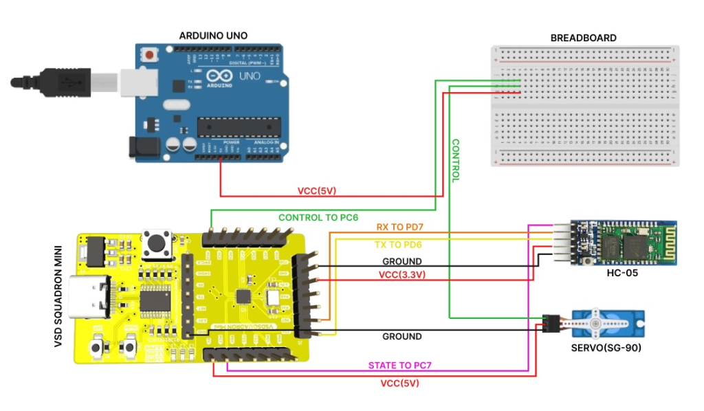
Arduino board here is given as an external power supply (additional 5V) to the control of the servo motor. Since this is outside the working power range for the SG90 motor, the circuitry is either damaged or the device shuts itself down to protect its internal wiring, hence simulating a fault in the system.
Fault Video
Protection against Fault
This fault can be protected by ensuring a safe enclosure where access is denied to manipulate the input voltage levels to the servo motor.
2. Inducing fault in HC-05 using potentiometer to corrupt receiver signal (RX)
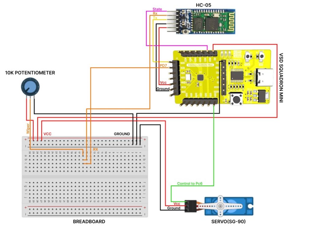
Another method is to inject noise into the signal lines of the HC-05 module. This can be done by connecting the potentiometer to the RX or TX lines. Connect the middle pin of the potentiometer to the RX pin of the HC-05 module, one of the outer pins of the potentiometer to a stable 5V power source and the other outer pin to GND. Adjust the potentiometer to vary the voltage on the RX pin, simulating noise or signal degradation to observe how the HC-05 module handles the noisy signal and it affects communication with the microcontroller.
Fault Video
Protection against Fault
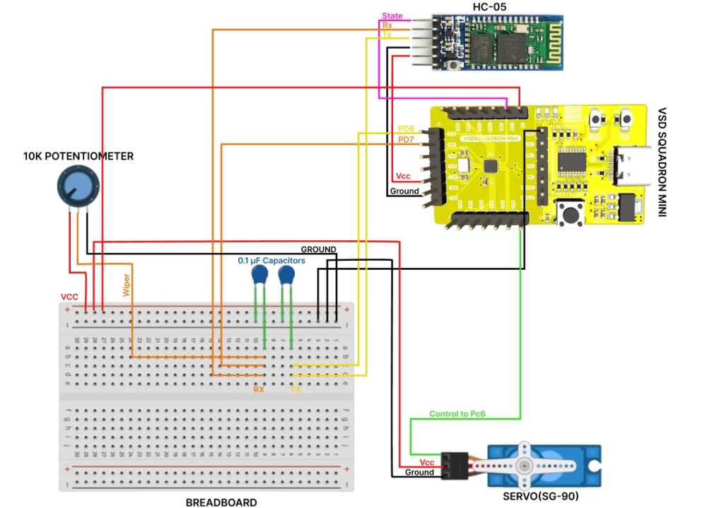
The capacitors added in this circuit act as a low pass filter which smoothen out any irregularities in the voltage fluctuations caused by varying the voltages levels in the potentiometer. The functioning of the circuit is hence optimised and the noise injected is managed efficiently.
Protection against Fault Video
3. Disrupting Bluetooth Signal using EM Waves

Bluetooth operates in the 2.4 GHz ISM band, which is shared with various other devices like Wi-Fi routers, microwaves, and cordless phones. This makes Bluetooth susceptible to electromagnetic interference (EMI).
EMI can cause disruptions in the Bluetooth signal, leading to data corruption, intermittent connections, or complete communication failure. The noise introduced by EMI can lead to an increase in the error rate of the transmitted and received data. The HC-05 module might behave erratically due to EMI, causing unexpected resets, incorrect data processing, or failure to connect to paired devices.
Protection against Fault
A Faraday cage can be employed to shield sensitive components of a Bluetooth device from external electromagnetic interference. By enclosing the components in a conductive material, the cage blocks external static and non-static electric fields. The cage should be made from materials with high electrical conductivity such as copper, aluminum, or conductive polymers and must be properly grounded to ensure that any absorbed EMI is safely conducted away from the device.
The mesh size of the cage needs to be smaller than the wavelength of the frequencies to be blocked (in the case of Bluetooth, smaller than 12.5 cm for effective shielding at 2.4 GHz). The mesh size of the cage needs to be smaller than the wavelength of the frequencies to be blocked (in the case of Bluetooth, smaller than 12.5 cm for effective shielding at 2.4 GHz). Thorough testing in environments with known EMI sources ensures the effectiveness of the Faraday cage and other shielding measures.
Result
The system successfully demonstrated resilience to simulated faults, maintaining security and stability. It locked the door upon detecting unauthorized commands and rebooted as expected under controlled conditions.
Conclusions
The implementation of robust fault injection and protection techniques significantly improved system reliability and security. These measures effectively mitigated risks associated with random reboots and unauthorized access, ensuring the system’s robustness in real-world scenarios.