Introduction
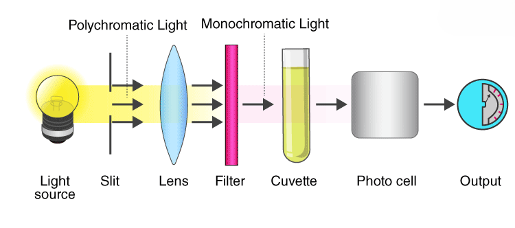
A colorimeter is a laboratory device used to measure the absorbance of light at specific wavelengths in a given solution. Colorimetry is based on Beer-Lambert’s law, which states that the amount of light absorbed by a colored solution is directly proportional to the solution’s concentration and the length of the light path through it. When light passes through a sample solution, part of it is absorbed, while the remaining light is transmitted. By comparing the color intensity of a solute in the sample solution to that of a reference solution with a known solute concentration, we can estimate the concentration of the colored solute in the sample. Colorimeters are commonly used in fields such as water analysis, environmental analysis, and laboratory research.
Colorimeters, if accessible to households, could be used for practical applications like food quality control, water testing, and gardening. For instance, they could help ensure the freshness of fruits based on their color, test the purity of tap water, or analyze soil nutrients for home gardening. These applications could contribute to health, food safety, and environmental conservation efforts at a personal level.
Overview of the Project
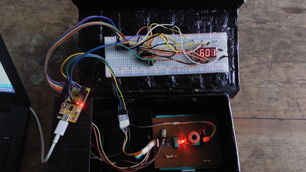
We are developing a colorimeter using an RGB LED to produce a spectrum of wavelengths by adjusting the intensity of the red, green, and blue LEDs individually. The emitted light passes through a solution sample in a cuvette positioned between the LED and a light-dependent resistor (LDR). LDR is a special resistor which creates variying voltage drop across it based on the intensity of incident light. The solution absorbs specific wavelengths based on the solute’s concentration and nature of the solute. Unabsorbed light is incident on the LDR , where voltage variations are recorded to calculate the corresponding intensity of a particular wavelength and hence the intesity across the spectrum. The analysis is performed in a closed black box to eliminate the external light sources from disturbing the analysis. A Zero Analysis is performed with only the pure solvent (e.g., distilled water), prior to performing actual analysis by placing the sample of the solute. Then the difference between the actual analysis and zero analysis is taken. This significantly reduces the the external noise from other light sources and defects in the RGB leds which do not produce the exact wavelength.
The wavelength and light intensity of the light are then displayed on a 4-bit 7-segment display. To efficiently transfer data to the display unit and minimize the number of pins required, we are using a Serial-In-Parallel-Out (SIPO) shift register.
Components Required
| Component | Quantity |
|---|---|
| VSD Squadron Mini Board | 1 |
| RGB LED (Common Cathode) | 1 |
| 1.1 KΩ Resistor | 5 |
| 11 KΩ Resistor | 1 |
| Light Dependent Resistor | 1 |
| 4 Bit Seven Segment Display | 1 |
| 74HC595 IC | 1 |
| Push Button | 1 |
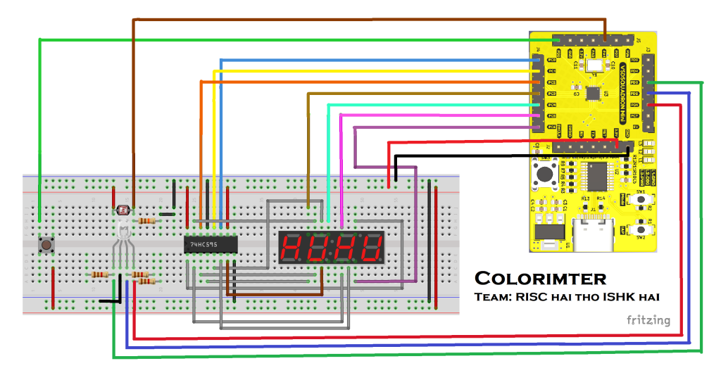
Circuit Connection Diagram
Tables for Pin connection
| VSD Squadron Mini | 74HC595 |
|---|---|
| 3.3 V | Pin 16 (Vcc) and Pin 10 (~Master Reset) |
| GND | Pin 8 (GND) and Pin 13 (~Output Enable) |
| PC0 | Pin 11 (Clock) |
| PC1 | Pin 12 (Latch Pin) |
| PC2 | Pin 14 (Serial Data In) |
| VSD Squadron Mini | 4 Bit Seven Segment Display |
|---|---|
| PC3 | D1 |
| PC4 | D2 |
| PC5 | D3 |
| PC6 | D4 |
| VSD Squadron Mini | RGB LED |
|---|---|
| PD1 | Red |
| PD3 | Green |
| PD2 | Blue |
| GND | Common Cathode |
| VSD Squadron Mini | Others |
|---|---|
| PD0 | Push Button (Signal) |
| PA1 | LDR (Signal) |
| GND | Push Button (GND) and LDR (GND) |
Working Video

Code
#include <ch32v00x.h>
#include <debug.h>

#define LED_RED GPIO_Pin_4
#define LED_GREEN GPIO_Pin_2
#define LED_BLUE GPIO_Pin_3

#define GPIO_PORT GPIOC
#define CLOCKPIN GPIO_Pin_0     //Pin 11 CLOCK
#define LATCHPIN GPIO_Pin_1		//Pin 12 latch
#define DATAPIN GPIO_Pin_2		//Pin 14 DataPin
#define DATA_1 GPIO_Pin_3		//D1
#define DATA_2 GPIO_Pin_4		//D2
#define DATA_3 GPIO_Pin_5		//D3
#define DATA_4 GPIO_Pin_6		//D4
#define CLOCK_ENABLE RCC_APB2PeriphClockCmd(RCC_APB2Periph_GPIOC, ENABLE)

#define ANALOG1_PIN     GPIO_Pin_1
#define ANALOG1_PORT    GPIOA

uint16_t adcReading;
int adcFlag, adc_int_val;

unsigned  char table[]={0x02,0x9E,0x24,0x0C,0x98,0x48,0x40,0x1E,0x00,0x08,0x77,0x7c,0x39,0x5e,0x79};
int  count = 2;
const int nbrDigits= 4;
void DisplayDigit(unsigned char num, int  digit);
void DisplayNumber(int number);

unsigned int reference_solution[6], solution[6], diff[6];
int absorbed_color_coeff, absorbed_color;
unsigned int wavelength[]={380, 450, 530, 570, 601, 670};

void shiftout(uint8_t dataPin, uint8_t clockPin, uint8_t bitOrder, uint8_t val)
{
	uint8_t i;

	for (i = 0; i < 8; i++)
	{
		if (bitOrder == 0)
				GPIO_WriteBit(GPIO_PORT, dataPin, !!(val & (1 << i)));
		else
				GPIO_WriteBit(GPIO_PORT, dataPin, !!(val & (1 << (7 - i))));

		GPIO_WriteBit(GPIO_PORT, CLOCKPIN, 1);
		GPIO_WriteBit(GPIO_PORT, CLOCKPIN, 0);
	}
}


void DisplayNumber(int number)
{
	if(number == 0)
		DisplayDigit( 0, nbrDigits-1) ; // display 0 in the rightmost digit
	else
	{
		for( int digit = nbrDigits-1; digit  >= 0; digit--)
		{
			if(number > 0)
			{
				DisplayDigit(number % 10, digit) ;
				number = number / 10;
			}
		}
	}

}


void DisplayDigit(unsigned char num, int  digit)
{
	GPIO_WriteBit(GPIO_PORT, LATCHPIN, 0);
	shiftout(DATAPIN, CLOCKPIN, 1, table[num]);
	GPIO_WriteBit(GPIO_PORT, LATCHPIN, 1);

    if(digit == 0)
	{
		GPIO_WriteBit(GPIO_PORT, DATA_1, 1);
		Delay_Ms(4);
		GPIO_WriteBit(GPIO_PORT, DATA_1, 0);
	}
    else if(digit == 1)
	{
		GPIO_WriteBit(GPIO_PORT, DATA_2, 1);
		Delay_Ms(4);
		GPIO_WriteBit(GPIO_PORT, DATA_2, 0);
	}
    else if(digit == 2)
	{
		GPIO_WriteBit(GPIO_PORT, DATA_3, 1);
		Delay_Ms(4);
		GPIO_WriteBit(GPIO_PORT, DATA_3, 0);
	}
    else if(digit == 3)
	{
		GPIO_WriteBit(GPIO_PORT, DATA_4, 1);
		Delay_Ms(4);
		GPIO_WriteBit(GPIO_PORT, DATA_4, 0);
	}
}

void ADCConfig(void)
{
    ADC_InitTypeDef ADC_InitStructure = {0};
    GPIO_InitTypeDef GPIO_InitStructureADC = {0};
    NVIC_InitTypeDef NVIC_InitStructure = {0};

    RCC_APB2PeriphClockCmd(RCC_APB2Periph_GPIOA, ENABLE);
    RCC_APB2PeriphClockCmd(RCC_APB2Periph_ADC1, ENABLE);
    RCC_ADCCLKConfig(RCC_PCLK2_Div8);

    GPIO_InitStructureADC.GPIO_Pin = ANALOG1_PIN;
    GPIO_InitStructureADC.GPIO_Mode = GPIO_Mode_AIN;
    GPIO_Init(ANALOG1_PORT, &GPIO_InitStructureADC);

    ADC_DeInit(ADC1);
    ADC_InitStructure.ADC_Mode = ADC_Mode_Independent;
    ADC_InitStructure.ADC_ScanConvMode = DISABLE;
    ADC_InitStructure.ADC_ContinuousConvMode = DISABLE;
    ADC_InitStructure.ADC_ExternalTrigConv = ADC_ExternalTrigInjecConv_None;
    ADC_InitStructure.ADC_DataAlign = ADC_DataAlign_Right;
    ADC_InitStructure.ADC_NbrOfChannel = 1;
    ADC_Init(ADC1, &ADC_InitStructure);

    ADC_InjectedSequencerLengthConfig(ADC1, 1);
    ADC_InjectedChannelConfig(ADC1, ADC_Channel_1, 1, ADC_SampleTime_241Cycles);
    ADC_ExternalTrigInjectedConvCmd(ADC1, DISABLE);

    NVIC_InitStructure.NVIC_IRQChannel = ADC_IRQn;
    NVIC_InitStructure.NVIC_IRQChannelPreemptionPriority = 2;
    NVIC_InitStructure.NVIC_IRQChannelSubPriority = 0;
    NVIC_InitStructure.NVIC_IRQChannelCmd = ENABLE;
    NVIC_Init(&NVIC_InitStructure);

    ADC_Calibration_Vol(ADC1, ADC_CALVOL_50PERCENT);
    ADC_ITConfig(ADC1, ADC_IT_JEOC, ENABLE);
    ADC_Cmd(ADC1, ENABLE);

    ADC_ResetCalibration(ADC1);

    while (ADC_GetResetCalibrationStatus(ADC1))
	{

	}

    ADC_StartCalibration(ADC1);

    while (ADC_GetCalibrationStatus(ADC1))
	{

	}
}

int ADCVal(void)
{
	ADC_SoftwareStartInjectedConvCmd(ADC1, ENABLE);
    if(adcFlag ==1)
	{
		adcReading = ADC_GetInjectedConversionValue(ADC1, ADC_InjectedChannel_1);
		adcFlag = 0;
	}
    adc_int_val=adcReading;
	return adc_int_val;
}

void ADC1_IRQHandler() __attribute__((interrupt("WCH-Interrupt-fast")));
void NMI_Handler(void) __attribute__((interrupt("WCH-Interrupt-fast")));
void HardFault_Handler(void) __attribute__((interrupt("WCH-Interrupt-fast")));
void Delay_Init(void);
void Delay_Ms(uint32_t n);

int main(void)
{
    NVIC_PriorityGroupConfig(NVIC_PriorityGroup_2);
    SystemCoreClockUpdate();
    Delay_Init();

    GPIO_InitTypeDef GPIO_InitStructure;
    RCC_APB2PeriphClockCmd(RCC_APB2Periph_GPIOD, ENABLE);
    GPIO_InitStructure.GPIO_Pin = LED_RED | LED_GREEN | LED_BLUE ;
    GPIO_InitStructure.GPIO_Mode = GPIO_Mode_Out_PP;
    GPIO_InitStructure.GPIO_Speed = GPIO_Speed_50MHz;
    GPIO_Init(GPIOD, &GPIO_InitStructure);

    GPIO_InitTypeDef GPIO_InitStructurePB;
    GPIO_InitStructurePB.GPIO_Pin = GPIO_Pin_0;
    GPIO_InitStructurePB.GPIO_Mode = GPIO_Mode_IPU;
    GPIO_InitStructurePB.GPIO_Speed = GPIO_Speed_50MHz;
    GPIO_Init(GPIOD, &GPIO_InitStructurePB);

    GPIO_InitTypeDef GPIO_InitStructure0 = {0};
    CLOCK_ENABLE;
    GPIO_InitStructure0.GPIO_Pin = CLOCKPIN;
    GPIO_InitStructure0.GPIO_Mode = GPIO_Mode_Out_PP;
    GPIO_InitStructure0.GPIO_Speed = GPIO_Speed_50MHz;
    GPIO_Init(GPIO_PORT, &GPIO_InitStructure0);

    GPIO_InitTypeDef GPIO_InitStructure1 = {0};
    CLOCK_ENABLE;
    GPIO_InitStructure1.GPIO_Pin = DATAPIN;
    GPIO_InitStructure1.GPIO_Mode = GPIO_Mode_Out_PP;
    GPIO_InitStructure1.GPIO_Speed = GPIO_Speed_50MHz;
    GPIO_Init(GPIO_PORT, &GPIO_InitStructure1);

    GPIO_InitTypeDef GPIO_InitStructure3 = {0};
    CLOCK_ENABLE;
    GPIO_InitStructure3.GPIO_Pin = LATCHPIN;
    GPIO_InitStructure3.GPIO_Mode = GPIO_Mode_Out_PP;
    GPIO_InitStructure3.GPIO_Speed = GPIO_Speed_50MHz;
    GPIO_Init(GPIO_PORT, &GPIO_InitStructure3);

    GPIO_InitTypeDef GPIO_InitStructure4 = {0};
    CLOCK_ENABLE;
    GPIO_InitStructure4.GPIO_Pin = DATA_1;
    GPIO_InitStructure4.GPIO_Mode = GPIO_Mode_Out_PP;
    GPIO_InitStructure4.GPIO_Speed = GPIO_Speed_50MHz;
    GPIO_Init(GPIO_PORT, &GPIO_InitStructure4);

    GPIO_InitTypeDef GPIO_InitStructure5 = {0};
    CLOCK_ENABLE;
    GPIO_InitStructure5.GPIO_Pin = DATA_2;
    GPIO_InitStructure5.GPIO_Mode = GPIO_Mode_Out_PP;
    GPIO_InitStructure5.GPIO_Speed = GPIO_Speed_50MHz;
    GPIO_Init(GPIO_PORT, &GPIO_InitStructure5);

    GPIO_InitTypeDef GPIO_InitStructure6 = {0};
    CLOCK_ENABLE;
    GPIO_InitStructure6.GPIO_Pin = DATA_3;
    GPIO_InitStructure6.GPIO_Mode = GPIO_Mode_Out_PP;
    GPIO_InitStructure6.GPIO_Speed = GPIO_Speed_50MHz;
    GPIO_Init(GPIO_PORT, &GPIO_InitStructure6);

    GPIO_InitTypeDef GPIO_InitStructure7 = {0};
    CLOCK_ENABLE;
    GPIO_InitStructure7.GPIO_Pin = DATA_4;
    GPIO_InitStructure7.GPIO_Mode = GPIO_Mode_Out_PP;
    GPIO_InitStructure7.GPIO_Speed = GPIO_Speed_50MHz;
    GPIO_Init(GPIO_PORT, &GPIO_InitStructure7);

    ADCConfig();

    GPIO_WriteBit(GPIOD, LED_RED|LED_BLUE, Bit_SET);
    GPIO_WriteBit(GPIOD, LED_GREEN, Bit_RESET);
    Delay_Ms(500);
    reference_solution[0]=ADCVal();
    for(int i=0; i<150; i++)
      DisplayNumber(reference_solution[0]);

    GPIO_WriteBit(GPIOD, LED_BLUE, Bit_SET);
    GPIO_WriteBit(GPIOD, LED_RED|LED_GREEN, Bit_RESET);
    Delay_Ms(500);
    reference_solution[1]=ADCVal();
    for(int i=0; i<150; i++)
      DisplayNumber(reference_solution[1]);

    GPIO_WriteBit(GPIOD, LED_BLUE|LED_GREEN, Bit_SET);
    GPIO_WriteBit(GPIOD, LED_RED, Bit_RESET);
    Delay_Ms(500);
    reference_solution[2]=ADCVal();
    for(int i=0; i<150; i++)
      DisplayNumber(reference_solution[2]);

    GPIO_WriteBit(GPIOD, LED_GREEN, Bit_SET);
    GPIO_WriteBit(GPIOD, LED_BLUE|LED_RED, Bit_RESET);
    Delay_Ms(500);
    reference_solution[3]=ADCVal();
    for(int i=0; i<150; i++)
      DisplayNumber(reference_solution[3]);

    GPIO_WriteBit(GPIOD, LED_RED|LED_GREEN, Bit_SET);
    GPIO_WriteBit(GPIOD, LED_BLUE, Bit_RESET);
    Delay_Ms(500);
    reference_solution[4]=ADCVal();
    for(int i=0; i<150; i++)
      DisplayNumber(reference_solution[4]);

    GPIO_WriteBit(GPIOD, LED_RED, Bit_SET);
    GPIO_WriteBit(GPIOD, LED_GREEN|LED_BLUE, Bit_RESET);
    Delay_Ms(500);
    reference_solution[5]=ADCVal();
    for(int i=0; i<150; i++)
      DisplayNumber(reference_solution[5]);

    while(GPIO_ReadInputDataBit(GPIOD, GPIO_Pin_0)!=0)
    {
      Delay_Ms(50);
    }

    GPIO_WriteBit(GPIOD, LED_RED|LED_BLUE, Bit_SET);
    GPIO_WriteBit(GPIOD, LED_GREEN, Bit_RESET);
    Delay_Ms(500);
    solution[0]=ADCVal();
    for(int i=0; i<150; i++)
      DisplayNumber(solution[0]);

    GPIO_WriteBit(GPIOD, LED_BLUE, Bit_SET);
    GPIO_WriteBit(GPIOD, LED_RED|LED_GREEN, Bit_RESET);
    Delay_Ms(500);
    solution[1]=ADCVal();
    for(int i=0; i<150; i++)
      DisplayNumber(solution[1]);

    GPIO_WriteBit(GPIOD, LED_BLUE|LED_GREEN, Bit_SET);
    GPIO_WriteBit(GPIOD, LED_RED, Bit_RESET);
    Delay_Ms(500);
    solution[2]=ADCVal();
    for(int i=0; i<150; i++)
      DisplayNumber(solution[2]);

    GPIO_WriteBit(GPIOD, LED_GREEN, Bit_SET);
    GPIO_WriteBit(GPIOD, LED_BLUE|LED_RED, Bit_RESET);
    Delay_Ms(500);
    solution[3]=ADCVal();
    for(int i=0; i<150; i++)
      DisplayNumber(solution[3]);

    GPIO_WriteBit(GPIOD, LED_RED|LED_GREEN, Bit_SET);
    GPIO_WriteBit(GPIOD, LED_BLUE, Bit_RESET);
    Delay_Ms(500);
    solution[4]=ADCVal();
    for(int i=0; i<150; i++)
      DisplayNumber(solution[4]);

    GPIO_WriteBit(GPIOD, LED_RED, Bit_SET);
    GPIO_WriteBit(GPIOD, LED_GREEN|LED_BLUE, Bit_RESET);
    Delay_Ms(500);
    solution[5]=ADCVal();
    for(int i=0; i<150; i++)
      DisplayNumber(solution[5]);

    absorbed_color_coeff=0;
    for(int i=0; i<6; i++)
    {
      diff[i]=solution[i]-reference_solution[i];
      if(diff[i]>diff[absorbed_color_coeff])
        absorbed_color_coeff=i;
    }
    absorbed_color=wavelength[absorbed_color_coeff];
    for(int i=0;i<250;i++)
      DisplayNumber(absorbed_color);
}

void ADC1_IRQHandler()
{
    if (ADC_GetITStatus(ADC1, ADC_IT_JEOC) == SET)
    {
        adcFlag = 1;
        ADC_ClearITPendingBit(ADC1, ADC_IT_JEOC);
    }
}

void NMI_Handler(void)
{

}

void HardFault_Handler(void)
{
	while (1)
	{
	}
}
https://github.com/lightningbolt0827/ShreyasM-TusharM_RISC_hai_tho_ISHK_hai
