Overview
The Smart Door project presents an innovative integration of infrared (IR) sensing technology with the CH32V003 RISC-V processor to create an automated door system. This system operates by detecting the presence of objects within its range using an IR sensor, which then sends signals to the CH32V003 RISC-V processor. Upon receiving these signals, the processor activates a servo motor to rotate and subsequently open or close the door, providing seamless and efficient access control. By combining these technologies, the project aims to offer users a convenient, secure, and automated solution for door operation, eliminating the need for manual intervention.

Components Required to build Smart Door:
- CH32V003X
- IR sensor
- Servo Motors (SG90)
- Power Supply
- Bread Board
- Jumper Wires
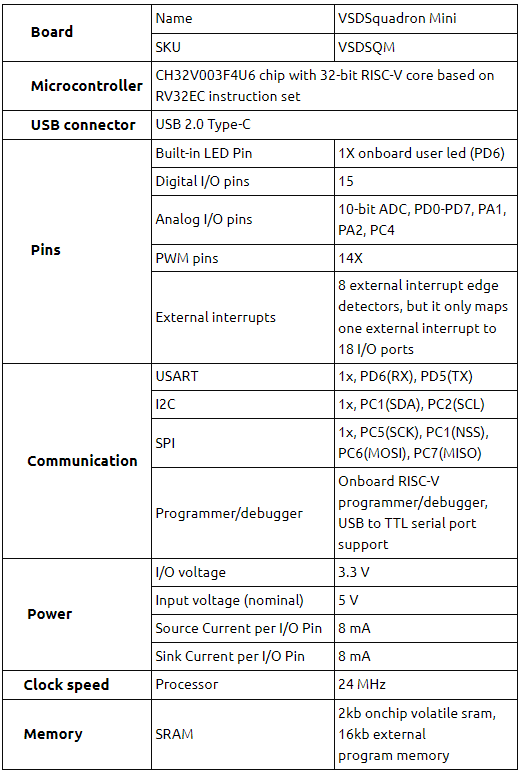
The CH32V003 RISC-V processor, employed in the smart door project, operates at voltages between 1.8V to 3.6V, featuring GPIO pins for interfacing with external devices and supporting communication protocols like SPI, I2C, and UART. The IR sensor utilized in the system typically operates at 3.3V or 5V, detecting infrared radiation emitted or reflected by objects within its range and converting it into electrical signals. The servo motor, integral to the project, operates within a voltage range of 4.8V to 6V and responds to PWM signals for position control, drawing current proportional to load and torque requirements. These electrical properties ensure compatibility and effective integration of components, facilitating the automated operation of the smart door system.
Circuit Connection for Smart Door
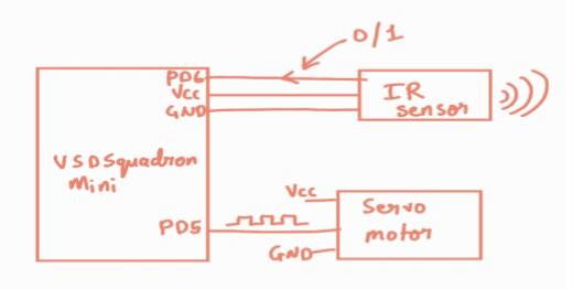
In the Smart Door project, the IR sensor is connected to the CH32V003 RISC-V processor as follows: The output pin of the IR sensor, which provides digital signals indicating object detection, is connected to the D3 pin of the CH32V003 processor. Additionally, the VCC (power) pin of the IR sensor is connected to the appropriate voltage supply pin (VCC) on the CH32V003, while the GND (ground) pin of the sensor is connected to the ground pin (GND) of the processor. This setup ensures that the CH32V003 can receive and process signals from the IR sensor, enabling it to detect objects in the vicinity.
Furthermore, the servo motor is connected to the CH32V003 processor as follows: The control pin (usually marked as PWM) of the servo motor, which receives PWM signals to control its position, is connected to the D2 pin of the CH32V003 processor. Additionally, the VCC pin of the servo motor is connected to the appropriate voltage supply pin (VCC) on the processor, while the GND pin of the motor is connected to the ground pin (GND) of the processor. This setup allows the CH32V003 processor to send PWM signals to the servo motor via the D2 pin, thereby controlling its rotation and enabling the automated opening and closing of the door.
Pinout Diagram for Smart Door

Table for Pin connection:
| Servo Motor (SG90) | CH32V003x |
|---|---|
| VCC (Red Wire) | VIN |
| PWM (Yellow Wire) | D2 |
| GND (Brown Wire) | GND |
| IR sensor | CH32V003x |
|---|---|
| VCC | VIN |
| OUT | D2 |
| GND | GND |
How to Program
These lines include header files, such as “ch32v00x.h”, providing access to CH32V00x-specific functions and definitions. Additionally, “debug.h” likely includes debugging-related functionalities for debugging and monitoring the code execution.
#include <ch32v00x.h>
#include <debug.h>
/* PWM Output Mode Definition */
#define PWM_MODE1 0
#define PWM_MODE2 1

/* PWM Output Mode Selection */
//#define PWM_MODE PWM_MODE1
#define PWM_MODE PWM_MODE2
This function initializes the PWM output on TIM1 peripheral, configuring GPIO pin D2 for alternate function push-pull output. It sets up the timer base with given period and pre-scaler values, and initializes the PWM output mode based on the selected PWM mode (PWM_MODE1 or PWM_MODE2). Finally, it enables PWM output, configures pulse width with the provided value, and enables the TIM1 peripheral for PWM output.
void GPIO_Config(void)
{
GPIO_InitTypeDef GPIO_InitStructure = {0};
void TIM1_PWMOut_Init(u16 arr, u16 psc, u16 ccp)
{
GPIO_InitTypeDef GPIO_InitStructure={0};
TIM_OCInitTypeDef TIM_OCInitStructure={0};
TIM_TimeBaseInitTypeDef TIM_TimeBaseInitStructure={0};

RCC_APB2PeriphClockCmd( RCC_APB2Periph_GPIOD, ENABLE ); GPIO_InitStructure.GPIO_Pin = GPIO_Pin_2;
GPIO_InitStructure.GPIO_Mode = GPIO_Mode_AF_PP; GPIO_InitStructure.GPIO_Speed = GPIO_Speed_10MHz;
GPIO_Init( GPIOD, &GPIO_InitStructure );

RCC_APB2PeriphClockCmd( RCC_APB2Periph_TIM1, ENABLE ); TIM_TimeBaseInitStructure.TIM_Period = arr; TIM_TimeBaseInitStructure.TIM_Prescaler = psc; TIM_TimeBaseInitStructure.TIM_ClockDivision = TIM_CKD_DIV1; TIM_TimeBaseInitStructure.TIM_CounterMode = TIM_CounterMode_Up; TIM_TimeBaseInit( TIM1, &TIM_TimeBaseInitStructure);

#if (PWM_MODE == PWM_MODE1)
TIM_OCInitStructure.TIM_OCMode = TIM_OCMode_PWM1;

#elif (PWM_MODE == PWM_MODE2)
TIM_OCInitStructure.TIM_OCMode = TIM_OCMode_PWM2;

#endif

TIM_OCInitStructure.TIM_OutputState = TIM_OutputState_Enable;
TIM_OCInitStructure.TIM_Pulse = ccp;
TIM_OCInitStructure.TIM_OCPolarity = TIM_OCPolarity_High;
TIM_OC1Init( TIM1, &TIM_OCInitStructure );
TIM_CtrlPWMOutputs(TIM1, ENABLE );
TIM_OC1PreloadConfig( TIM1, TIM_OCPreload_Disable );
TIM_ARRPreloadConfig( TIM1, ENABLE );
TIM_Cmd( TIM1, ENABLE );
}

RCC_APB2PeriphClockCmd(RCC_APB2Periph_GPIOD, ENABLE);
GPIO_InitStructure.GPIO_Pin = GPIO_Pin_3;
GPIO_InitStructure.GPIO_Mode = GPIO_Mode_IPU;
GPIO_Init(GPIOD, &GPIO_InitStructure);

GPIO_InitStructure.GPIO_Pin = GPIO_Pin_6;
GPIO_InitStructure.GPIO_Mode = GPIO_Mode_Out_PP;
GPIO_InitStructure.GPIO_Speed = GPIO_Speed_50MHz;
GPIO_Init(GPIOD, &GPIO_InitStructure);
}
This function configures GPIO pins on Port D of the microcontroller. It enables the clock for Port D, initializes pin D3 as an input with pull-up resistor enabled, and configures pin D6 as an output with push-pull configuration and a speed of 50MHz.
void GPIO_Config(void)

{

GPIO_InitTypeDef GPIO_InitStructure = {0};

RCC_APB2PeriphClockCmd(RCC_APB2Periph_GPIOD, ENABLE);
GPIO_InitStructure.GPIO_Pin = GPIO_Pin_3;
GPIO_InitStructure.GPIO_Mode = GPIO_Mode_IPU;
GPIO_Init(GPIOD, &GPIO_InitStructure);

GPIO_InitStructure.GPIO_Pin = GPIO_Pin_6;
GPIO_InitStructure.GPIO_Mode = GPIO_Mode_Out_PP GPIO_InitStructure.GPIO_Speed = GPIO_Speed_50MHz;
GPIO_Init(GPIOD, &GPIO_InitStructure);

}
This is the main function of the program. It initializes necessary components, such as the system clock, delays, and GPIO configurations. Then, it enters a continuous loop where it reads the status of input pin D3. If the input is low (indicating an object detected by the IR sensor), it blinks an LED connected to pin D6 and initializes a PWM output on TIM1 with a duty cycle of 95%. If the input is high (no object detected), it turns off the LED and initializes the PWM output with a duty cycle of 10%. The loop repeats with a delay of 100 milliseconds between iterations.
int main(void)
{
 uint8_t GPIOInputStatus = 0;
 NVIC_PriorityGroupConfig(NVIC_PriorityGroup_2);
 SystemCoreClockUpdate();
 Delay_Init(); GPIO_Config();

 while(1)
 {
  GPIOInputStatus = GPIO_ReadInputDataBit(GPIOD,GPIO_Pin_3);
  if(GPIOInputStatus == 0)

   {
    GPIO_WriteBit(GPIOD, GPIO_Pin_6, SET);
    // blink led TIM1_PWMOut_Init( 100, 480-1, 95);
    //10% dutycycle pwm out
   }
   else
   {
    GPIO_WriteBit(GPIOD, GPIO_Pin_6, RESET);
    TIM1_PWMOut_Init( 100, 480-1, 10);
    //95% dutyclycle pwm out
   }

  Delay_Ms(100);
  }
 }
void NMI_Handler(void) {}
void HardFault_Handler(void)
   {
    while (1)
   {
   }
 }
Smart Door – Working
In the Smart Door project, the IR sensor continuously monitors for the presence of an object. When the sensor detects an object, it sends a signal to the CH32V003 microcontroller. Upon receiving this signal, the microcontroller commands the
servo motor, which is likely attached to the door, to open the door. Conversely, when no object is detected by the IR sensor, indicating that the area is clear, the microcontroller commands the servo motor to return the door to its closed position. This automated process ensures that the door opens only when an object is detected and closes when the area is clear, providing convenience and security in accessing the space.
Code
#include <ch32v00x.h>
#include <debug.h>

/* PWM Output Mode Definition */
#define PWM_MODE1 0
#define PWM_MODE2 1
/* PWM Output Mode Selection */
//#define PWM_MODE PWM_MODE1
#define PWM_MODE PWM_MODE2

// Configuration for Timer 1 void TIM1_PWMOut_Init(u16 arr, u16 psc, u16 ccp)

{

GPIO_InitTypeDef GPIO_InitStructure={0};
TIM_OCInitTypeDef TIM_OCInitStructure={0};
TIM_TimeBaseInitTypeDef TIM_TimeBaseInitStructure={0};

RCC_APB2PeriphClockCmd( RCC_APB2Periph_GPIOD, ENABLE );
GPIO_InitStructure.GPIO_Pin = GPIO_Pin_2;
GPIO_InitStructure.GPIO_Mode = GPIO_Mode_AF_PP; //alternate mode
GPIO_InitStructure.GPIO_Speed = GPIO_Speed_10MHz;
GPIO_Init( GPIOD, &GPIO_InitStructure );

RCC_APB2PeriphClockCmd( RCC_APB2Periph_TIM1, ENABLE );
TIM_TimeBaseInitStructure.TIM_Period = arr;
TIM_TimeBaseInitStructure.TIM_Prescaler = psc;
TIM_TimeBaseInitStructure.TIM_ClockDivision = TIM_CKD_DIV1;
TIM_TimeBaseInitStructure.TIM_CounterMode = TIM_CounterMode_Up;
TIM_TimeBaseInit( TIM1, &TIM_TimeBaseInitStructure);

#if (PWM_MODE == PWM_MODE1) TIM_OCInitStructure.TIM_OCMode = TIM_OCMode_PWM1;

#elif (PWM_MODE == PWM_MODE2) TIM_OCInitStructure.TIM_OCMode = TIM_OCMode_PWM2;

#endif TIM_OCInitStructure.TIM_OutputState = TIM_OutputState_Enable;

TIM_OCInitStructure.TIM_Pulse = ccp;
TIM_OCInitStructure.TIM_OCPolarity = TIM_OCPolarity_High;
TIM_OC1Init( TIM1, &TIM_OCInitStructure );
TIM_CtrlPWMOutputs(TIM1, ENABLE );
TIM_OC1PreloadConfig( TIM1, TIM_OCPreload_Disable );
TIM_ARRPreloadConfig( TIM1, ENABLE );
TIM_Cmd( TIM1, ENABLE );

}

void GPIO_Config(void)
{

GPIO_InitTypeDef GPIO_InitStructure = {0};
//structure variable used for the GPIO configuration
RCC_APB2PeriphClockCmd(RCC_APB2Periph_GPIOD, ENABLE); // to Enable the clock for Port D

GPIO_InitStructure.GPIO_Pin = GPIO_Pin_3; // Defines which Pin to configure

GPIO_InitStructure.GPIO_Mode = GPIO_Mode_IPU; // Defines Output Type
GPIO_Init(GPIOD, &GPIO_InitStructure);
GPIO_InitStructure.GPIO_Pin = GPIO_Pin_6; // Defines which Pin to configure

GPIO_InitStructure.GPIO_Mode = GPIO_Mode_Out_PP; // Defines Output Type

GPIO_InitStructure.GPIO_Speed = GPIO_Speed_50MHz; // Defines speed
GPIO_Init(GPIOD, &GPIO_InitStructure);

}

int main(void)
{

uint8_t GPIOInputStatus = 0;
NVIC_PriorityGroupConfig(NVIC_PriorityGroup_2);
SystemCoreClockUpdate();
Delay_Init();
GPIO_Config();

 while(1)
 {
  GPIOInputStatus = GPIO_ReadInputDataBit(GPIOD,GPIO_Pin_3);
  if(GPIOInputStatus == 0)

 {
  GPIO_WriteBit(GPIOD, GPIO_Pin_6, SET);
  // blink led TIM1_PWMOut_Init( 100, 480-1, 10);
 //10% dutycycle pwm out
 }
 else
 {
 GPIO_WriteBit(GPIOD, GPIO_Pin_6, RESET);
 TIM1_PWMOut_Init( 100, 480-1, 95);  //95% dutyclycle pwm out
 }

 Delay_Ms(100);
 }
 }

void NMI_Handler(void)
{
}

void HardFault_Handler(void)
 {
   while (1)
   {

   }
 }
