BCD
BCD stands for Binary-Coded Decimal. A BCD counter is a type of counter used in digital electronics and computing to represent decimal numbers using binary-coded decimal format. In BCD format, each decimal digit (0-9) is represented by a 4-bit binary code.
Example:
- Decimal
0is represented as0000in BCD. - Decimal
4is represented as0100in BCD. - Decimal
15is represented as0001 0101in BCD.
The Counter
Overview
Counters are fundamental components in digital electronics that are used to count, sequence, or track events. They play a crucial role in various electronic systems and have several applications across different fields including Frequency measurement & division, Event counting and monitoring etc,. I have created a BCD counter that counts from 0 to 99. When a push button (which act as clock) is pressed, the counter increments by one.
Components Required
- VSD Mini Squadron Board
- 8 LEDs ( 4 Blue & 4 Red )
- Eight 220 ohm Resistors
- Push button switch
- Jumper cables
- Bread board
- USB type-C or a 3.3V DC power source
Hardware Connections

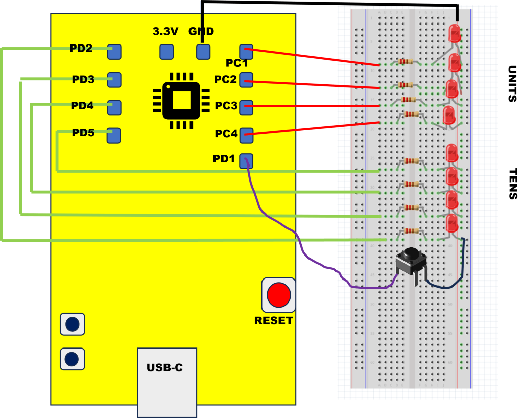
As we can see from the above image,
- A push button which act as
triggeris connected betweenGND&PD1. - All the 8 LEDs have a common
GND& each of their Anode is connected to a 220 ohms resistors. - Ports
PC0toPC3forms theunitdigit & are connected to their respective LEDs withPC0being LSB (Least Significant Bit) &PC3being MSB (Most Significant Bit) - Similarly, Ports
PD2toPD5forms thetensdigit & are connected to their respective LEDs withPD2being LSB (Least Significant Bit) &Pbeing MSB (Most Significant Bit)
The Code To Program The Board
As we know the VSD Mini Board can be programmed in embedded C, below is the C code which programs the board to act as a BCD counter.
#include <ch32v00x.h>

// Define GPIO pins for the LEDs
#define UNIT_LSB_PIN GPIO_Pin_0  // LSB of the units digit
#define UNIT_MSB_PIN GPIO_Pin_3  // MSB of the units digit
#define TENS_LSB_PIN GPIO_Pin_2  // LSB of the tens digit
#define TENS_MSB_PIN GPIO_Pin_5  // MSB of the tens digit

// Function to initialize GPIO pins
void GPIO_Config(void) {
    GPIO_InitTypeDef GPIO_InitStructure;
    RCC_APB2PeriphClockCmd(RCC_APB2Periph_GPIOD | RCC_APB2Periph_GPIOC | RCC_APB2Periph_GPIOD, ENABLE);

    // Configure the reading pin on port D as digital input
    GPIO_InitStructure.GPIO_Pin = GPIO_Pin_1;
    GPIO_InitStructure.GPIO_Mode = GPIO_Mode_IPU; // Input with pull-up
    GPIO_Init(GPIOD, &GPIO_InitStructure);

    // Configure LEDs for units digit on port C as output
    GPIO_InitStructure.GPIO_Pin = UNIT_LSB_PIN | GPIO_Pin_1 | GPIO_Pin_2 | UNIT_MSB_PIN;
    GPIO_InitStructure.GPIO_Mode = GPIO_Mode_Out_PP;
    GPIO_InitStructure.GPIO_Speed = GPIO_Speed_50MHz;
    GPIO_Init(GPIOC, &GPIO_InitStructure);

    // Configure LEDs for tens digit on port D as output
    GPIO_InitStructure.GPIO_Pin = TENS_LSB_PIN | GPIO_Pin_3 | GPIO_Pin_4 | TENS_MSB_PIN;
    GPIO_Init(GPIOD, &GPIO_InitStructure);
}

// Function to update the BCD counter display
void UpdateDisplay(uint8_t tens, uint8_t units) {
    GPIO_Write(GPIOC, (GPIO_ReadOutputData(GPIOC) & 0xFFF0) | units); // Write units digit to port C
    GPIO_Write(GPIOD, (GPIO_ReadOutputData(GPIOD) & 0xFFC3) | (tens << 2));  // Write tens digit to port D
}

// Simple delay function
void delay(uint32_t count) {
    while(count--) {
        __NOP(); // Do nothing (NOP instruction)
    }
}

int main(void) {
    uint8_t units = 0, tens = 0;
    int prevButtonState = 1; // Initialize to high

    GPIO_Config(); // Configure the GPIO

    while(1) {
        // Read the button state from pin D1
        int buttonState = GPIO_ReadInputDataBit(GPIOD, GPIO_Pin_1);

        // Detect negative edge (1 to 0 transition)
        if(!buttonState && prevButtonState) {
            // Increment the BCD counter
            units++;
            if(units > 9) {
                units = 0;
                tens++;
                if(tens > 9) {
                    tens = 0;
                }
            }
            UpdateDisplay(tens, units); // Update the BCD display
        }
        prevButtonState = buttonState; // Update the previous button state

        delay(10000); // Debounce delay
    }
}
Working & Demo Video
The board is programmed to continuously monitor the voltage/state at port PD1. Upon detecting a negedge, which is the transition of voltage from 3.3v to 0v, it will increment the counter to the next state. This can be observed in the below video.


