Overview
This project involves the implementation of Full Adder combinational circuit using VSDSquadron Mini, a RISCV based SoC development kit. Full Adder is a very important circuit in digital electronics, widely used in creating the design of n-bits Adder circuit. A full adder circuit is a digital circuit that adds two binary digits and a carry-in digit to produce a sum and carry-out digit. It’s a central component of most digital circuits that perform addition or subtraction. This project demonstrates the practical application of digital logic and RISC-V architecture in executing arithmetic operation, reflecting the process of reading and writing of binary data through GPIO pins, implementing the operation of full adder through digital logic gates which is simulated using PlatformIO IDE and thus displaying the outputs using LEDs.
Components Required
- VSDSquadron Mini
- Push Buttons for Input of binary data
- 2 LEDs for displaying the Output
- Breadboard
- Jumper Wires
- VS Code for Software Development
- PlatformIO multi framework professional IDE
Hardware Connections
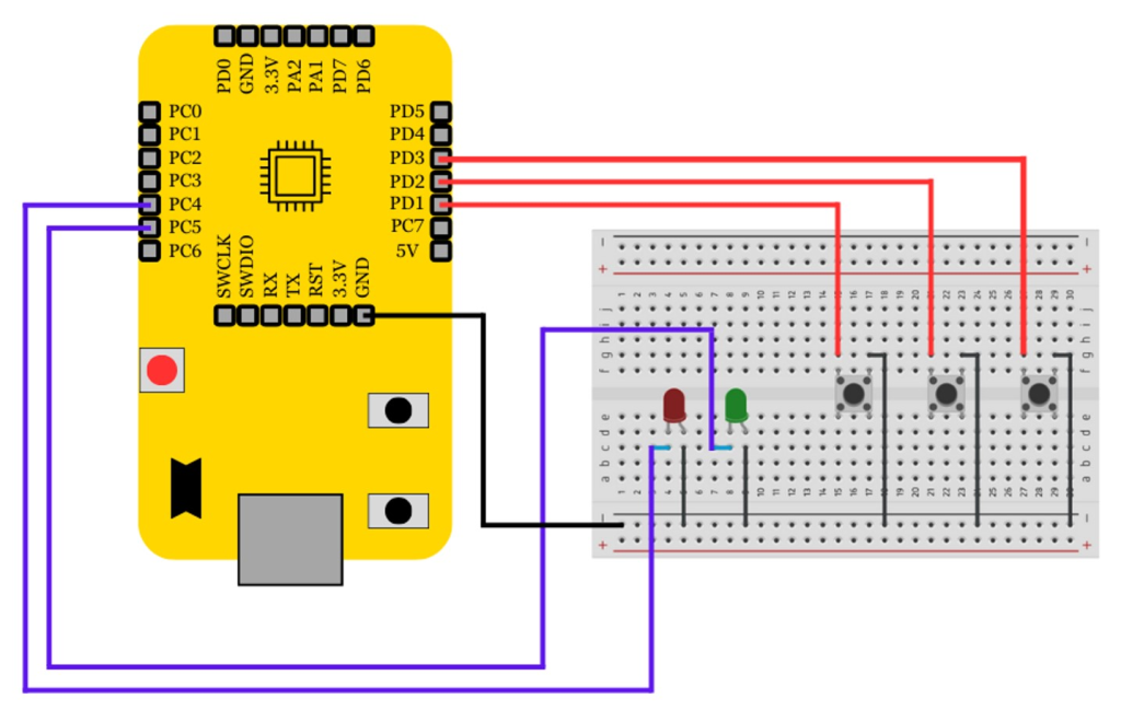
- Input: Three input of single bit are connected to the GPIO pins of VSDSquadron Mini via push buttons mounted on the breadboard.
- Outputs: Two LEDs are connected to display the result of Full Adder
- The GPIO pins are configured according to the Reference Mannual, ensuring the correct flow of signals between the components

Truth Table to Verify the Full Adder
| A | B | Cin | Sum | Carry |
|---|---|---|---|---|
| 0 | 0 | 0 | 0 | 0 |
| 0 | 0 | 1 | 1 | 0 |
| 0 | 1 | 0 | 1 | 0 |
| 0 | 1 | 1 | 0 | 1 |
| 1 | 0 | 0 | 1 | 0 |
| 1 | 0 | 1 | 0 | 1 |
| 1 | 1 | 0 | 0 | 1 |
| 1 | 1 | 1 | 1 | 1 |
How to Program?
// Full Adder Implementation

// Included the requried header files
#include<stdio.h>
#include<debug.h>
#include<ch32v00x.h>

// Defining the Logic Gate Function
int and(int bit1, int bit2)
{
    int out = bit1 & bit2;
    return out;
}
int or(int bit1, int bit2)
{
    int out = bit1 | bit2;
    return out;
}
int xor(int bit1, int bit2)
{
    int out = bit1 ^ bit2;
    return out;
}

// Configuring GPIO Pins
void GPIO_Config(void)
{
    GPIO_InitTypeDef GPIO_InitStructure = {0}; // structure variable used for GPIO configuration
    RCC_APB2PeriphClockCmd(RCC_APB2Periph_GPIOD, ENABLE); // to enable the clock for port D
    RCC_APB2PeriphClockCmd(RCC_APB2Periph_GPIOC, ENABLE); // to enable the clock for port C

    // Input Pins Configuration
    GPIO_InitStructure.GPIO_Pin = GPIO_Pin_1 | GPIO_Pin_2 | GPIO_Pin_3;
    GPIO_InitStructure.GPIO_Mode = GPIO_Mode_IPU; // Defined as Input Type
    GPIO_Init(GPIOD, &GPIO_InitStructure);

    //Output Pins Configuration
    GPIO_InitStructure.GPIO_Pin = GPIO_Pin_4 | GPIO_Pin_5;
    GPIO_InitStructure.GPIO_Mode = GPIO_Mode_Out_PP; // Defined Output Type
    GPIO_InitStructure.GPIO_Speed = GPIO_Speed_50MHz; // Defined Speed
    GPIO_Init(GPIOC, &GPIO_InitStructure);
}

// The MAIN function responsible for the execution of program
int main()
{
    uint8_t A, B, Cin, Sum, Carry; // Declared the required variables
    uint8_t p, q, r, s, t;
    NVIC_PriorityGroupConfig(NVIC_PriorityGroup_2);
    SystemCoreClockUpdate();
    Delay_Init();
    GPIO_Config();

    while(1)
    {
        A = GPIO_ReadInputDataBit(GPIOD, GPIO_Pin_1);
        B = GPIO_ReadInputDataBit(GPIOD, GPIO_Pin_2);
        Cin = GPIO_ReadInputDataBit(GPIOD, GPIO_Pin_3);
        s = xor(A, B);
        Sum = xor(Cin, s);
        p = and(A, B);
        q = and(B, Cin);
        r = and(Cin, A);
        t = or(p, q);
        Carry = or(r, t);

        /* SUM */
        if(Sum == 0)
        {
            GPIO_WriteBit(GPIOC, GPIO_Pin_4, SET);
        }
        else
        {
            GPIO_WriteBit(GPIOC, GPIO_Pin_4, RESET);
        }

        /* CARRY */
        if(Carry == 0)
        {
            GPIO_WriteBit(GPIOC, GPIO_Pin_5, SET);
        }
        else
        {
            GPIO_WriteBit(GPIOC, GPIO_Pin_5, RESET);
        }
    }
}


