Overview
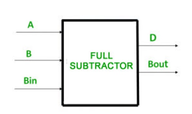
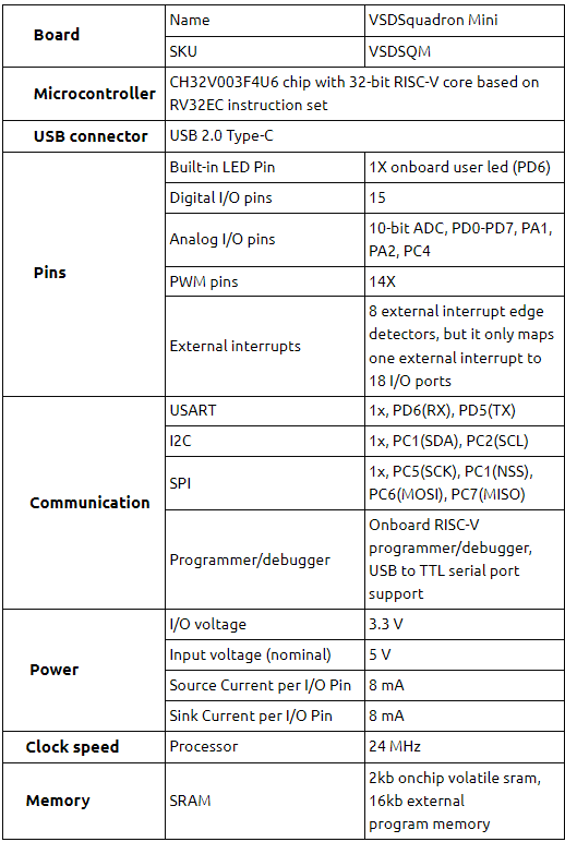
This project involves the implementation of a Full Subtractor combinational circuit using VSDSquadron Mini, a RISCV based SoC development kit. Full Subtractor is an essential component in digital electronics, commonly employed in designing n-bit Subtracter circuits. A full subtractor circuit is a digital circuit that subtracts two binary digits and a borrow-in digit to produce a difference and borrow-out digit. It serves as a crucial element in digital circuits performing subtraction operations. This project showcases the practical application of digital logic and RISC-V architecture in executing arithmetic operations. It demonstrates the process of reading and writing binary data through GPIO pins, implementing the operation of full subtractor through digital logic gates simulated using PlatformIO IDE, and displaying the outputs using LEDs.
Components Required
- VSDSquadron Mini board
- Push Buttons
- 2 LEDs
- Breadboard
- Jumper Wires
- VS Code , Platformio
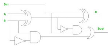
Logical Diagram and Expressions

D = (A XOR B) XOR Bin
= A’B’Bin + A’BBin’ + AB’Bin’ + ABBin
= Bin(A’B’ + AB)  + Bin’(AB’ + A’B)
= Bin( A XNOR B) + Bin’(A XOR B)
= Bin (A XOR B)’  +  Bin’(A XOR B)
= Bin XOR (A XOR B)
= (A XOR B) XOR Bin
Bout= A’Bin + A’B + BBin
 = A’B’Bin + A’BBin’ + A’BBin + ABBin
 = A’B’Bin +A’BBin’ + A’BBin + A’BBin + A’BBin + ABBin
 = A’Bin(B + B’) + A’B(Bin + Bin’) + BBin(A + A’)
 = A’Bin + A’B + BBin
Hardware Connections
| VSDSquadron Mini Board | Hardware Connections |
|---|---|
| GND | LED1 anode, LED2 anode, Switch(1,2,3) anode |
| PD1 | Switch 1 cathode (A) |
| PD2 | Switch 2 cathode (B) |
| PD3 | Switch 3 cathode (Bin) |
| PC4 | Red LED (Borrow) |
| PC5 | Green LED (Difference) |
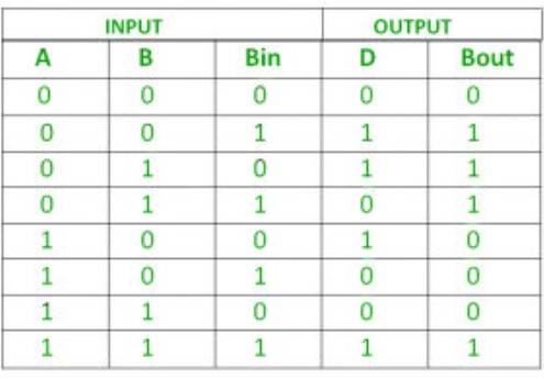
Truth Table to Verify the Full Subtractor

Program
// Full Subtractor Implementation

// Included the required header files
#include <stdio.h>
#include <debug.h>
#include <ch32v00x.h>

// Defining the Logic Gate Functions
int and(int bit1, int bit2)
{
    int out = bit1 & bit2;
    return out;
}
int or(int bit1, int bit2)
{
    int out = bit1 | bit2;
    return out;
}
int xor(int bit1, int bit2)
{
    int out = bit1 ^ bit2;
    return out;
}
int not(int bit)
{
    int out = ~bit & 1; // Ensuring only the least significant bit is considered
    return out;
}

// Configuring GPIO Pins
void GPIO_Config(void)
{
    GPIO_InitTypeDef GPIO_InitStructure = {0}; // structure variable used for GPIO configuration
    RCC_APB2PeriphClockCmd(RCC_APB2Periph_GPIOD, ENABLE); // to enable the clock for port D
    RCC_APB2PeriphClockCmd(RCC_APB2Periph_GPIOC, ENABLE); // to enable the clock for port C

    // Input Pins Configuration
    GPIO_InitStructure.GPIO_Pin = GPIO_Pin_1 | GPIO_Pin_2 | GPIO_Pin_3;
    GPIO_InitStructure.GPIO_Mode = GPIO_Mode_IPU; // Defined as Input Type with pull-up
    GPIO_Init(GPIOD, &GPIO_InitStructure);

    // Output Pins Configuration
    GPIO_InitStructure.GPIO_Pin = GPIO_Pin_4 | GPIO_Pin_5;
    GPIO_InitStructure.GPIO_Mode = GPIO_Mode_Out_PP; // Defined Output Type
    GPIO_InitStructure.GPIO_Speed = GPIO_Speed_50MHz; // Defined Speed
    GPIO_Init(GPIOC, &GPIO_InitStructure);
}

// The MAIN function responsible for the execution of the program
int main()
{
    uint8_t A, B, Bin, Diff, Bout; // Declared the required variables
    uint8_t p, q, r;
    NVIC_PriorityGroupConfig(NVIC_PriorityGroup_2);
    SystemCoreClockUpdate();
    Delay_Init();
    GPIO_Config();

    while(1)
    {
        A = GPIO_ReadInputDataBit(GPIOD, GPIO_Pin_1);
        B = GPIO_ReadInputDataBit(GPIOD, GPIO_Pin_2);
        Bin = GPIO_ReadInputDataBit(GPIOD, GPIO_Pin_3);

        // Full Subtractor Logic
        Diff = xor(xor(A, B), Bin); // Difference = A ⊕ B ⊕ Bin
        p = and(not(A), B); // p = A' B
        q = and(B, Bin); // q = B Bin
        r = and(not(A), Bin); // r = A' Bin
        Bout = or(or(p, q), r); // Borrow out = A' B + B Bin + A' Bin

        // Write the Difference output
        if(Diff == 1)
        {
            GPIO_WriteBit(GPIOC, GPIO_Pin_4, RESET); // LED on for Difference = 1
        }
        else
        {
            GPIO_WriteBit(GPIOC, GPIO_Pin_4, SET); // LED off for Difference = 0
        }

        // Write the Borrow output
        if(Bout == 1)
        {
            GPIO_WriteBit(GPIOC, GPIO_Pin_5, RESET); // LED on for Borrow out = 1
        }
        else
        {
            GPIO_WriteBit(GPIOC, GPIO_Pin_5, SET); // LED off for Borrow out = 0
        }
    }
}
Application Video
Related Posts:
- Shape Tomorrow’s Technology Today: ELCIA Hackathon…
- PARKinSENSE
- RISC-V Mini Game Console
- The Future of Chip Design: The Next Generation is…
- Smart Plant Care using the VSD_Squadron-MINI-BOARD
- LiFi Lock - An authentication system using LiFi…
- Soldiers Health Monitoring and GPS Tracking System
- Making a Game Console Using VSDSquadron Mini
- Home safety system
- Real Time Implementation of BitNetMCU


