Hey There,
This is rather a very curious query I had, when I was learning Magic VLSI Layout tool, and I am very sure, every fresher layout engineer back there, will have a similar curiosity.
I went ahead and had a detailed discussion about this with Tim Edwards, SVP Analog at Efabless Corp. Pvt. Ltd.
Here’s how it went:
Question) I am referring to your below comment in “Magic Maintainer’s Manual #3: Display Styles, Colormaps, and Glyphs”

Where is the man page?
I do not see it under below link
http://www.opencircuitdesign.com/magic/index.html
Answer) If you install from source, the man page ends up in the usual place (or what used to be the usual place) in /usr/local/man/. I can convert the man pages on my system to HTML and post them on the “Documentation” page. There are a number of them, including ones on the .ext and .sim formats, ext2spice and ext2sim, and so forth. You will now find it there under “Documentation” (button in the frame on the left). The man pages are rather outdated; I need to go update them sometime. But at least I have them in HTML format on the website now.
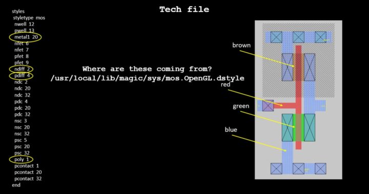
Question) The thing, I am trying to do here is find out the below mapping (for eg. nwell 12, what does ’12’ refer to)
styles
styletype mos
nwell 12
pwell 13
metal1 20
nfet 6
nfet 7
pfet 8
pfet 9
ndiff 2
pdiff 4
ndc 2
ndc 20
ndc 32
pdc 4
pdc 20
pdc 32
nsc 3
nsc 20
nsc 32
psc 5
psc 20
psc 32
poly 1
pcontact 1
pcontact 20
pcontact 32
end
Answer) I always found the numbers to be very confusing, so I changed the format to use the style names instead of numbers (but it’s backwards-compatible). The numbers (and names) come from the “dstyle” file, which in a standard install will be in:
/usr/local/lib/magic/sys/mos.OpenGL.dstyle
for the OpenGL interface, and
/usr/local/lib/magic/sys/mos.24bit.dstyle
otherwise (the “7bit” graphics can only be used by a graphics card that can do 8-bit overlays on top of a 24-bit visual. Old Matrox cards used to support this back in the early 2000’s, but I haven’t seen any
recently, and Matrox went out of business a long time ago. I coded in a whole bunch of bit-block transfer routines to make the 24-bit graphics fast once I realized that 8-bit overlays were gone and not coming back).
Anyway, in the .dstyle file, you’ll find lines that look like this:
# num opaque color outline fill number name name
#———————————————————————-
10 63 6 0x00 stipple 7 – cwell
52 92 2 0x00 stipple 19 – cwellnsc
79 63 4 0x00 stipple 21 – highvolt_nwell
80 63 5 0x00 stipple 22 – highvolt_pwell
12 63 2 0xff stipple 2 – nwell
Note the last line I copied above from the file. . . This is the number 12 in the “styles” section you quoted. The more “modern” way to write the style section is
styles
styletype mos
nwell nwell
Which is also a bit confusing, but the first “nwell” is the layer type, and the second “nwell” is the style name. It would probably make more sense if the layer name was called “yellow_sparse_stripes” or something.
Question) In tech file, for pcontact, I see below
pcontact 1
pcontact 20
pcontact 32
Whereas in dstyle file, I see below
# num opaque color outline fill number name name
#———————————————————————-
74 127 45 0x00 solid 0 – pcontact
Are the numbers (1, 20, 32) in tech file coming because of color coding of below overlaps?
# num opaque color outline fill number name name
#———————————————————————-
1 120 1 0x00 solid 0 – polysilicon
20 80 8 0x00 solid 0 – metal1
32 92 7 0xff cross 0 – contact_X’es
Answer) Yes. As I said, I think it would be better if the “name” entry says something about what the pattern and color looks like, such as “yellow-sparse-stripes”. So number 74 “pcontact” is a purple color that blends the blue of metal1 and the red of poly. It’s a nice style to use for poly contacts, which is why the style is called “pcontact”. But the OpenGL graphics blends colors together anyway, so style “polysilicon” (which is solid red) and style “metal1” (which is solid light blue) blended together also make a nice purple color, so the combination of those styles works just as well.
In general, the 2nd form is easier to work with, since for any contact, you can just blend the two colors of the layers that make up the contact, then add some boundary or X or stipple pattern to make it stand out as a contact.
—————————
Now you see, how asking the right questions helps….
All above discussion is also captured in form of online course below:
https://www.udemy.com/vlsi-academy-custom-layout/
All the best and happy learning…

