Introduction
Trash bins, whether termed dustbins, garbage receptacles, or trash cans, serve as essential containers for temporarily housing waste in a variety of settings, including households, workplaces, public spaces, and outdoor areas. They fulfill a vital role in waste management, particularly in regions where littering is prohibited, serving as the primary means for disposing of small waste items. Traditionally, waste segregation practices often involve the use of separate bins for wet and dry waste, as well as for recyclable and non-recyclable materials, contributing to efficient waste management and recycling efforts.
Overview
The Smart Dustbin project showcased here introduces an innovative solution utilizing a VSD Squadron Mini Development Board, an Ultrasonic Sensor, and a Servo Motor. Its core functionality lies in its ability to autonomously open the lid of the dustbin upon detecting the presence of a human hand. Central to the project is the principle of object detection. Here, an Ultrasonic Sensor is strategically placed atop the dustbin’s lid. When the sensor detects an object, such as a human hand, it triggers the VSD Squadron Mini to activate the Servo Motor, thereby initiating the lid-opening mechanism. This technology-driven approach offers a hands-free and user-friendly solution for waste disposal, potentially enhancing hygiene and sanitation practices across various settings. Its implementation holds promise for streamlining waste management processes and fostering a cleaner and more sustainable environment.
Components Required
- VSD Squadron Mini development board with CH32V003F4U6 chip with 32-bit RISC-V core based on RV32EC instruction set
- HC-SR04 Ultrasonic Sensor
- 500 RPM Gear Motor
- L298N Motor Driver Module
- External Power Supply
- Bread Board
- Jumper Wires
Software Required
- MounRiver Studio
- To download the studio Click Here
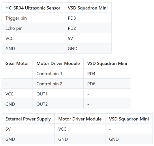
Table for Pin connection

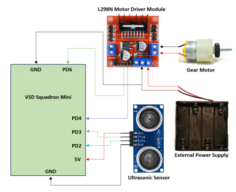
Circuit Connection Diagram

Design of the Project
The trigger and echo pins of the Ultrasonic sensor are connected to PD3 and PD2 pins of the VSD Squadron Mini respectively. The VCC and GND pins are connected to the 5V and GND pins of the development board.
As a gear motor is used in this project, an external supply is needed to power it. Additionally, to control the motor actuations, a L298N motor driver module is used. The motor is connected to the OUT1 and OUT2 of the motor driver module. Furthermore, the input stimuli is given through the VSD Squadron Mini for which the IN1 and IN2 ports are connected to PD4 and PD6 of the development board (NOTE: PD6 is connected to the on board LED. Hence, this port is intentionally chosen to work as a debug LED).
Finally, the motor setup is powered by an external power supply of 6V which is connected to the 12V (port supporting up to 12V) and GND ports of the motor driver module. Completing the connection, the motor driver module and the VSD Squadron mini are connected to the common GND.
Working Code
//Including Libraries
#include "debug.h"

//Function to configure GPIO Pins
void GPIO_Toggle_INIT(void)
{
    GPIO_InitTypeDef GPIO_InitStructure = {0};   ////Structure variable used for the GPIO configuration

    RCC_APB2PeriphClockCmd(RCC_APB2Periph_GPIOD, ENABLE);  ////To Enable the clock for Port D

    GPIO_InitStructure.GPIO_Pin = GPIO_Pin_6 | GPIO_Pin_4 | GPIO_Pin_3; //// Defining Pins to configure
    GPIO_InitStructure.GPIO_Mode = GPIO_Mode_Out_PP;  ///// Setting Pin mode as Output type
    GPIO_InitStructure.GPIO_Speed = GPIO_Speed_50MHz;  ////Defining GPIO Speed   -----NOTE: There are three options: GPIO_Speed_10MHz, GPIO_Speed_2MHz, GPIO_Speed_50MHz
    GPIO_Init(GPIOD, &GPIO_InitStructure);    ////Instantiating the GPIO pins with the structure variable

    GPIO_InitStructure.GPIO_Pin = GPIO_Pin_2;  //// Instantiation of Pins
    GPIO_InitStructure.GPIO_Mode = GPIO_Mode_IPU;  ///// Setting Pin mode as Input type
    GPIO_Init(GPIOD, &GPIO_InitStructure);    ////Instantiating the GPIO pins with the structure variable


}

//Main Function
int main(void)
{

    NVIC_PriorityGroupConfig(NVIC_PriorityGroup_1);
    SystemCoreClockUpdate(); //// Configure MCU Clock HSI
    Delay_Init();    ////Dealy for allowing clock to Stabilize

//USART initialization
#if (SDI_PRINT == SDI_PR_OPEN)
    SDI_Printf_Enable();
#else
    USART_Printf_Init(115200);
#endif
    printf("SystemClk:%d\r\n", SystemCoreClock);
    printf( "ChipID:%08x\r\n", DBGMCU_GetCHIPID() );

    //Calling Function to Configure GPIO Pins
    GPIO_Toggle_INIT();

    while(1)
    {
        u8 i = 0, j = 0, k = 0;  //// Declaring local Variables

        GPIO_WriteBit(GPIOD, GPIO_Pin_3, SET);  //// Setting Trigger Pin to send pulses
        Delay_Ms(10);      ///// Pulse Width
        k = GPIO_ReadInputDataBit(GPIOD, GPIO_Pin_2); //// Reading pulse captured by echo pin

        if (k  == 0){

            Delay_Ms(1000);   //// Delay to Synchronise with the Clock

            //Defining condition for Motor Spin Direction
            GPIO_WriteBit(GPIOD, GPIO_Pin_6, (i == 0) ? (i = Bit_SET) : (i = Bit_RESET));
            GPIO_WriteBit(GPIOD, GPIO_Pin_4, (j == 0) ? (j = Bit_RESET) : (j = Bit_SET));
            Delay_Ms(1300);

            //Defining condition to stop Motor
            GPIO_WriteBit(GPIOD, GPIO_Pin_6, (i == 0) ? (i = Bit_SET) : (i = Bit_RESET));
            GPIO_WriteBit(GPIOD, GPIO_Pin_4, (j == 0) ? (j = Bit_RESET) : (j = Bit_SET));
            Delay_Ms(5000);

            //Defining condition for Motor Spin Direction
            GPIO_WriteBit(GPIOD, GPIO_Pin_4, (i == 0) ? (i = Bit_SET) : (i = Bit_RESET));
            GPIO_WriteBit(GPIOD, GPIO_Pin_6, (j == 0) ? (j = Bit_RESET) : (j = Bit_SET));
            Delay_Ms(1300);

            //Defining condition to stop Motor
            GPIO_WriteBit(GPIOD, GPIO_Pin_6, (i == 0) ? (i = Bit_SET) : (i = Bit_RESET));
            GPIO_WriteBit(GPIOD, GPIO_Pin_4, (j == 0) ? (j = Bit_RESET) : (j = Bit_SET));
            Delay_Ms(4000);
        }

        //Conditions to disable motor actuation
        if (k != 0){

            Delay_Ms(1000); //// Delay to Synchronise with the Clock

            //Defining condition to stop Motor
            GPIO_WriteBit(GPIOD, GPIO_Pin_4, (i == 0) ? (i = Bit_SET) : (i = Bit_RESET));
            GPIO_WriteBit(GPIOD, GPIO_Pin_6, (j == 0) ? (j = Bit_SET) : (j = Bit_RESET));
            Delay_Ms(4000);
        }
        //Resetting Trigger Pin
        GPIO_WriteBit(GPIOD, GPIO_Pin_3, RESET);
        Delay_Ms(5);
    }
}


