Hello,
Hope you liked my previous post on “SPEF Format”, and, there had been 4 days since my last post, so I believe the previous one is well absorbed. With that said, let’s move on with identifying the path components of net connected to Din2 port shown below

For now, let’s have a distributed RC network representation of the net (shown below). We do have another way of representing RC network in reduced format. I will come back to that in a moment

Now that we know the components of Din2_net, lets write down the SPEF equivalent of this net. Firstly, we will map the name “Din2_net” as “*2” and use “*2” hence forth, to refer to Din2_net.

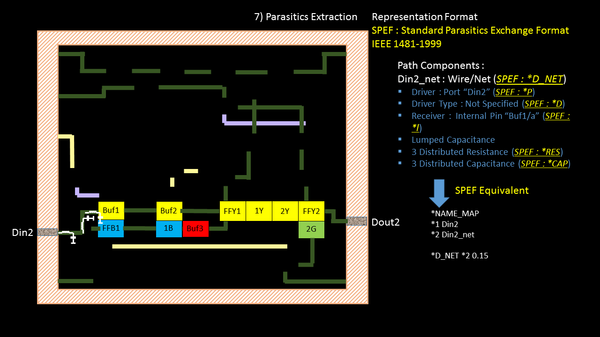
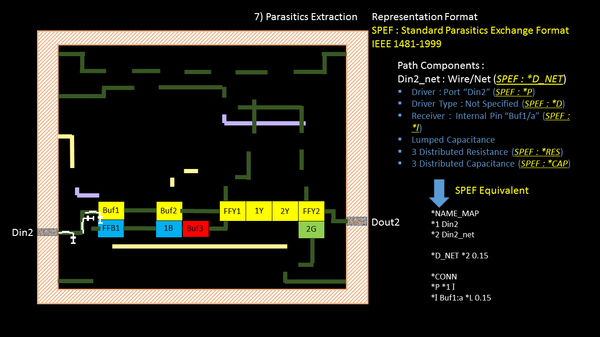
We will come back to how do we calculate the load value of “0.15”. *D_NET denotes “distributed net”. If we had used a reduced format of the nets, with only single value of resistance and capacitance, it would had been called as “*R_NET”.Now lets write down the connectivity information of “Din2_net” or “*2”.*CONN section defines connectivity of *2

The below says. *2 (Din2_net) is connected to external port (*P), named *1 (port Din2), which has direction “input” (I)

The other end of net “*2” is connected to internal pin “Buf1:a” and having a load (*L) of 0.15 units. I will come back later on the “units” section, in my following post

This becomes a part of the SPEF file, so lets put it in a file, that we were maintaining from last post
Subcribe & Download complete eBookYour email address is 100% safe from spam!

What next? Oh, remember, we have to represent the below distributed RC network in a standard SPEF format as well. So let’s do it !!
OR, let’s take a quick break over here. Honestly, we did a lot of work above. So lets “revise and relearn”, till I get back with the next post, continuing from this point. Even, “Rome wasn’t built in a day, but they were laying bricks every hour” You got me right !!
Happy Learning !!
Kunal


