Water level monitoring and control in water tank
Introduction
A water level monitoring system uses an ultrasonic sensor to measure the distance to the water surface in a tank. The VSD Squadron Mini Developement Board processes this data to determine the water level. If the level drops below a certain threshold, the system can activate a servo motor to refill the tank. It alerts users with an LED or buzzer when the water level is low, ensuring efficient water management.
Components Required
-VSD Squadron Mini developement board -Servo motor -HC-SR04 Ultrasonic Sensor -External Power Supply -Bread Board -Jumper Wires
Circuit Connection Diagram
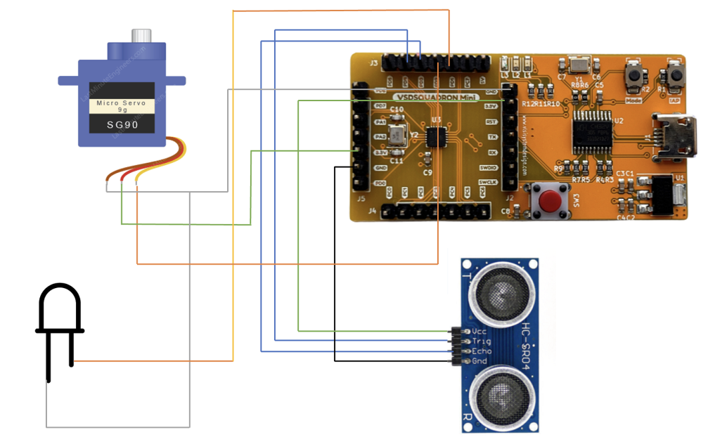
Table for Pin connection
| HC-SR04 Ultrasonic Sensor | VSD Squadron Mini |
|---|---|
| Trigger pin | PD4 |
| Echo pin | PD3 |
| VCC | 3.3V |
| GND | GND |
| Servo Motor | VSD Squadron Mini |
|---|---|
| Control pin | PD2 |
| OUT1 | VCC |
| OUT2 | GND |
| BULB | VSD Squadron Mini |
|---|---|
| OUT1 | PD6 |
| OUT2 | GND |
code
#include <ch32v00x.h>
#include <debug.h>

/* PWM Output Mode Definition */
#define PWM_MODE1 0
#define PWM_MODE2 1
/* PWM Output Mode Selection */
#define PWM_MODE PWM_MODE2

/* Threshold distance in cm for water level */
#define WATER_LEVEL_THRESHOLD 10

/* Function to initialize PWM on Timer 1 for the servo motor */
void TIM1_PWMOut_Init(uint16_t arr, uint16_t psc, uint16_t ccp)
{
    GPIO_InitTypeDef GPIO_InitStructure = {0};
    TIM_OCInitTypeDef TIM_OCInitStructure = {0};
    TIM_TimeBaseInitTypeDef TIM_TimeBaseInitStructure = {0};

    RCC_APB2PeriphClockCmd(RCC_APB2Periph_GPIOD, ENABLE);
    GPIO_InitStructure.GPIO_Pin = GPIO_Pin_2;
    GPIO_InitStructure.GPIO_Mode = GPIO_Mode_AF_PP; // Alternate Function Push-Pull
    GPIO_InitStructure.GPIO_Speed = GPIO_Speed_10MHz;
    GPIO_Init(GPIOD, &GPIO_InitStructure);

    RCC_APB2PeriphClockCmd(RCC_APB2Periph_TIM1, ENABLE);
    TIM_TimeBaseInitStructure.TIM_Period = arr;
    TIM_TimeBaseInitStructure.TIM_Prescaler = psc;
    TIM_TimeBaseInitStructure.TIM_ClockDivision = TIM_CKD_DIV1;
    TIM_TimeBaseInitStructure.TIM_CounterMode = TIM_CounterMode_Up;
    TIM_TimeBaseInit(TIM1, &TIM_TimeBaseInitStructure);

#if (PWM_MODE == PWM_MODE1)
    TIM_OCInitStructure.TIM_OCMode = TIM_OCMode_PWM1;
#elif (PWM_MODE == PWM_MODE2)
    TIM_OCInitStructure.TIM_OCMode = TIM_OCMode_PWM2;
#endif
    TIM_OCInitStructure.TIM_OutputState = TIM_OutputState_Enable;
    TIM_OCInitStructure.TIM_Pulse = ccp;
    TIM_OCInitStructure.TIM_OCPolarity = TIM_OCPolarity_High;
    TIM_OC1Init(TIM1, &TIM_OCInitStructure);
    TIM_CtrlPWMOutputs(TIM1, ENABLE);
    TIM_OC1PreloadConfig(TIM1, TIM_OCPreload_Disable);
    TIM_ARRPreloadConfig(TIM1, ENABLE);
    TIM_Cmd(TIM1, ENABLE);
}

/* Function to configure GPIO Pins */
void GPIO_Config(void)
{
    GPIO_InitTypeDef GPIO_InitStructure = {0};

    RCC_APB2PeriphClockCmd(RCC_APB2Periph_GPIOD, ENABLE);

    // Pin 3: Input for Ultrasonic sensor echo
    GPIO_InitStructure.GPIO_Pin = GPIO_Pin_3;
    GPIO_InitStructure.GPIO_Mode = GPIO_Mode_IPU; // Input with Pull-Up
    GPIO_Init(GPIOD, &GPIO_InitStructure);

    // Pin 4: Output for Ultrasonic sensor trigger
    GPIO_InitStructure.GPIO_Pin = GPIO_Pin_4;
    GPIO_InitStructure.GPIO_Mode = GPIO_Mode_Out_PP; // Output Push-Pull
    GPIO_InitStructure.GPIO_Speed = GPIO_Speed_50MHz;
    GPIO_Init(GPIOD, &GPIO_InitStructure);

    // Pin 6: LED indicator
    GPIO_InitStructure.GPIO_Pin = GPIO_Pin_6;
    GPIO_InitStructure.GPIO_Mode = GPIO_Mode_Out_PP; // Output Push-Pull
    GPIO_InitStructure.GPIO_Speed = GPIO_Speed_50MHz;
    GPIO_Init(GPIOD, &GPIO_InitStructure);
}

/* Function to trigger the ultrasonic sensor and read the echo duration */
uint32_t Ultrasonic_Read(void)
{
    uint32_t echoTime = 0;

    GPIO_WriteBit(GPIOD, GPIO_Pin_4, SET); // Setting Trigger Pin to send pulses
    Delay_Us(10); // Pulse Width
    GPIO_WriteBit(GPIOD, GPIO_Pin_4, RESET); // Resetting Trigger Pin

    while (GPIO_ReadInputDataBit(GPIOD, GPIO_Pin_3) == Bit_RESET); // Wait for Echo to go high
    while (GPIO_ReadInputDataBit(GPIOD, GPIO_Pin_3) == Bit_SET) echoTime++; // Measure the time Echo is high

    return echoTime;
}

/* Function to calculate distance from echo time */
float Calculate_Distance(uint32_t echoTime)
{
    // Speed of sound in air is 340 m/s or 0.034 cm/us
    // Distance is (time / 2) * speed_of_sound
    return (echoTime / 2.0) * 0.034;
}

/* Function to control LED blinking */
void Blink_LED(uint8_t times, uint16_t on_time, uint16_t off_time)
{
    for (uint8_t i = 0; i < times; i++)
    {
        GPIO_WriteBit(GPIOD, GPIO_Pin_6, Bit_SET); // Turn LED on
        Delay_Ms(on_time); // Delay for on_time

        GPIO_WriteBit(GPIOD, GPIO_Pin_6, Bit_RESET); // Turn LED off
        Delay_Ms(off_time); // Delay for off_time
    }
}

/* Main function */
int main(void)
{
    NVIC_PriorityGroupConfig(NVIC_PriorityGroup_2);
    SystemCoreClockUpdate();
    Delay_Init();
    GPIO_Config();
    USART_Printf_Init(115200); // Initialize debug USART

    while (1)
    {
        uint32_t echoTime = Ultrasonic_Read();
        float distance = Calculate_Distance(echoTime);

        printf("Distance: %.2f cm\n", distance); // Print the distance

        if (distance < WATER_LEVEL_THRESHOLD) // If water level is below the threshold
        {
            Blink_LED(3, 200, 100); // Blink LED three times with specified on and off times
            TIM1_PWMOut_Init(100, 480 - 1, 95); // Set PWM to 95% duty cycle to activate the servo motor
        }
        else
        {
            GPIO_WriteBit(GPIOD, GPIO_Pin_6, Bit_RESET); // Turn off LED
            TIM1_PWMOut_Init(100, 480 - 1, 10 ); // Set PWM to 10% duty cycle to deactivate the servo motor
        }

        Delay_Ms(1000); // Wait for 1 second before next reading
    }
}
video
https://github.com/kaushik-97/Tandav_VSD_IIITB-Ethical-RISC-V-IoT-Hackathon